Cv controller communications, Figure 4-7: cv controller component locations – Auto-Zone Control Systems Auto-Zone CV & CV-EX Systems Installation & Operation (Version 01C) User Manual
Page 86
Section 4
Auto-Zone CV & CV-EX
4-8
Start-Up and Troubleshooting
CV Controller Communications
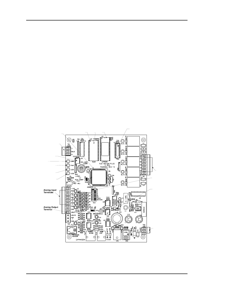
One CV controller is required for each Constant Volume AHU unit to be connected to the
system. As with the communications devices on the system described previously, it must
be wired correctly, and it must be connected to 24 VAC power for the system to function.
Each controller must also be addressed correctly. Improper addressing is one of the most
common mistakes made when installing a CV or CV-EX system. If duplicate addresses
are assigned on the same loop, fluctuating readings will occur. First, one controller’s
setpoints and status will be passed and then the other. This can be a very frustrating error
to find. Another common mistake is flipping (reversing) of the T and R wires on the
communication loop between controllers or other communications devices. Always be
sure to double-check all communication wiring and addressing before initial
commissioning of the system. It is much easier to set the address switch on a controller
prior to installation than after it is installed in a ceiling or rooftop unit control panel. The
address switches must be set and the power cycled in order for the address to be recog-
nized by the system. Please see Figure 4-7 and Figure 4-8 for CV Controller component
location and addressing information.
Relay Outputs
Terminals
Diagnostic Blink
Code LED 1
Diagnostic Blink
Code LED 2
RS-485
Communications
Terminal Block
CPU
Chip
Typical
Pin 1
Indicator
RAM
Chip
EPROM
Chip
PAL
Chip
RS-485
Communications
Driver Chip
Real Time
Clock Chip
Communications
LED
Address Switch
Power LED
24 VAC
Power Input
Terminal
Figure 4-7:
CV Controller Component Locations