Commlink iv dip switch setting – Auto-Zone Control Systems Auto-Zone CV & CV-EX Systems Installation & Operation (Version 01C) User Manual
Page 83
Auto-Zone CV & CV-EX
Section 4
Start-Up and Troubleshooting
4-5
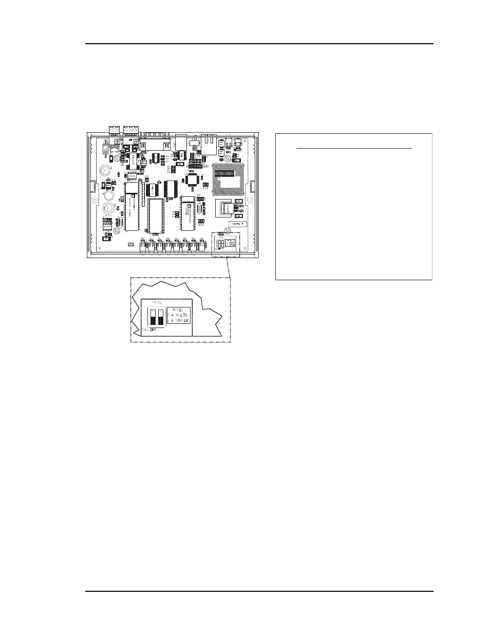
CommLink IV DIP Switch Setting
DIP Switch 1 & 2 Off =
Multiple Loop Communications
Required Setting For Auto-Zone CV-EX System
CommLink IV Communication Settings
The SW1 DIP Switch Located On The Circuit Board Inside
The CommLink IV Housing Must Be Set Correctly For
Your Specific Application In Order To Function Properly.
To Check And/Or Set The SW1 Dip Switch, First Remove
The (2) Enclosure Screws That Hold The Top And Bottom
Of The CommLink IV Enclosure Together. Remove The
Top Half Of The Enclosure To Access The Circuit Board
And Dip Switches.
The
DIP Switch Setting Should Be Set To “Multiple”
For The Auto-Zone
System
The CommLink IV Is Factory Set For Multiple Loop
Applications.
SW1
CV-EX
.
Replace The CommLink IV Cover And Secure The
Enclosure Halves Back Together With The (2) Enclosure
Screws That Were Previously Removed.
ALTERA
EPM3032
WattMaster Controls Inc.
COMMLINK IV
YS102074
REV6
MADE IN USA
Figure 4-4:
CommLink IV DIP Switch Setting