Minilink interface, Auto-zone cv & cv-ex 2-24 installation and wiring, Figure 2-18: minilink interface overview – Auto-Zone Control Systems Auto-Zone CV & CV-EX Systems Installation & Operation (Version 01C) User Manual
Page 36
Section 2
Auto-Zone CV & CV-EX
2-24
Installation and Wiring
MiniLink Interface
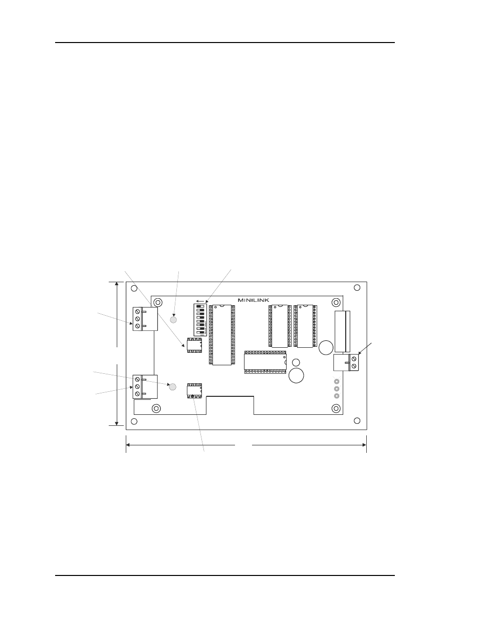
The MiniLink Interface is only required and used with the CV-EX system. It is not
required for the CV system. It functions as the loop master for each CV-EX system local
loop. With the CV-EX system, each local loop of CV controllers (maximum of 30) is
connected to a MiniLink. Two MiniLinks are supplied with the standard CV-EX system.
This allows up to 60 CV controllers (30 maximum per local loop) to be tied together to
form an integrated system. A CV-EX expansion kit is available which provides another
MiniLink to allow an additional 30 CV controllers to be connected to the system. A
maximum of two expansion kits can be used on the CV-EX system to provide integration
of up to 120 CV controllers. See Figure 2-18 for an overview of the MiniLink.
24 VAC
Power
Network Loop
Communications
Driver Chip
Network Loop
Communications
LED
Local Loop
Communications
LED
Local Loop
Communications
Driver Chip
Address Switch
( Each Board Must Be Addressed Uniquely )
( 1,2,3,4)
Switch Shown Set For Address 1
Local Loop
Connector
Network Loop
Connector
7.50”
4.
50
"
LO
O
P
24VAC
GND
T
SH
R
32
16
8
4
1
2
OFF >
ADD
NETWORK
SH
T
R
Figure 2-18:
MiniLink Interface Overview