Auto-zone cv & cv-ex 2-20 installation and wiring, Figure 2-14: commlink iv wiring for cv system – Auto-Zone Control Systems Auto-Zone CV & CV-EX Systems Installation & Operation (Version 01C) User Manual
Page 32
Section 2
Auto-Zone CV & CV-EX
2-20
Installation and Wiring
MODEM
RS-232
Serial #
COMPUTER
USB
10/100
ETHERNET
DIAG
24V
T G R
GN
D
485 LOOP POWER
ACT
LNK
USB
Conf
ig
Nor
m
al
Local
Comm Loop
T
R
SH
IEL
D
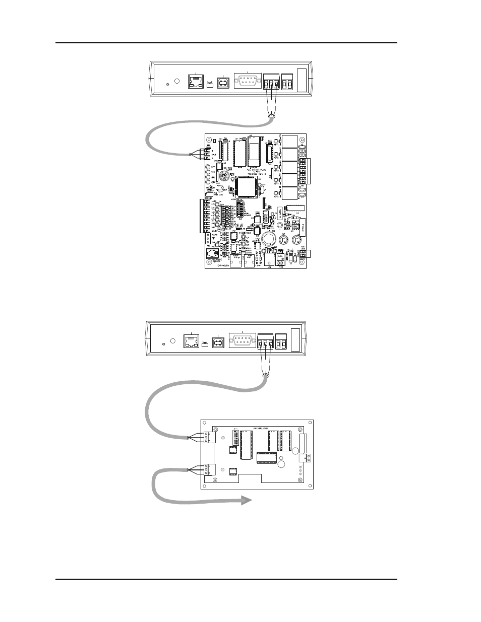
Figure 2-14:
CommLink IV Wiring for CV System
MODEM
RS-232
Serial #
COMPUTER
USB
10/100
ETHERNET
DIAG
24V
T G R
GN
D
485 LOOP POWER
ACT
LNK
USB
Co
nf
ig
No
rm
al
Local Communications Loop
To CV Controllers
And System Manager
Network
Comm Loop
Local
Comm Loop
T
R
SH
IEL
D
LO
O
P
24VAC
GND
T
SH
R
32
16
8
4
1
2
OFF >
MiniLink Communications Interface
ADD
NETWORK
SH
T
R
Figure 2-15:
CommLink IV to MiniLink Wiring for CV-EX System