Cv-ex system, Figure 4-2: cv-ex system communications wiring – Auto-Zone Control Systems Auto-Zone CV & CV-EX Systems Installation & Operation (Version 01C) User Manual
Page 81
Auto-Zone CV & CV-EX
Section 4
Start-Up and Troubleshooting
4-3
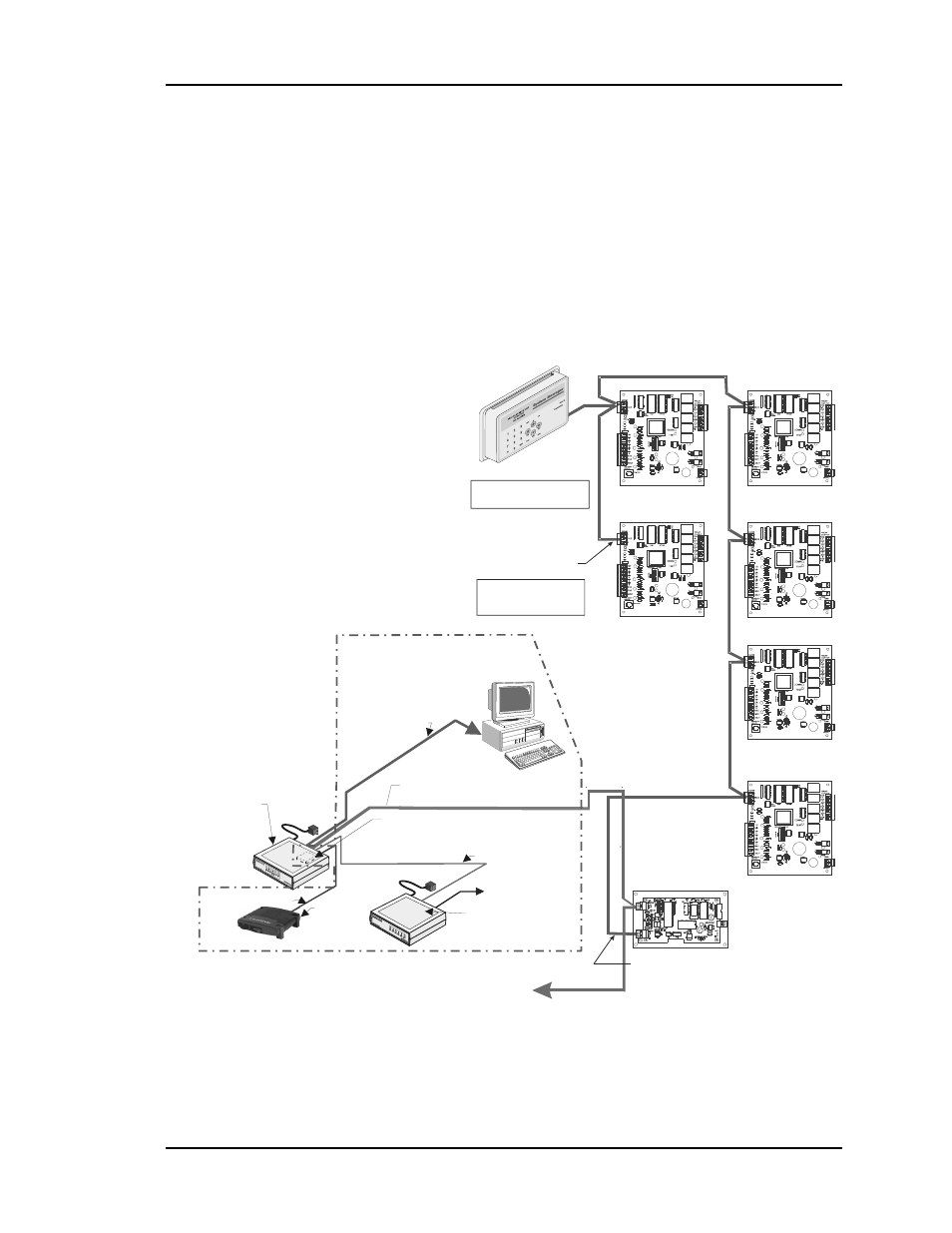
CV-EX System
See Figure 4-2. The CV-EX system has two types of communications loops. The loops
which the CV controllers are connected to are called the Local Loops. The MiniLink is
always the loop master on the CV-EX local loop. You must be sure the MiniLink is
connected, powered up, and functioning if you are troubleshooting a Local communica-
tions loop. The other type of loop on the CV-EX system is called the Network Loop. This
loop connects all the MiniLinks together and then ties into the CommLink IV which is
the Network Loop Master. The CommLink IV jumper switch must be set for multiple
loop operation when used with the CV-EX system. See Figure 4-4 for the correct jumper
switch setting.
Computer
(Optional)
End Of Local Loop
MiniLink
RS-485
9600 Baud
RS-485
19200 Baud
Local Loop
Network Loop Start
Network Loop
Connect To
Network Loop
Connection On
Next MiniLink
Local Loop Start
CV Controller
CV Controller
CV Controller
CV Controller
CV Controller
CV Controller
System Manager
The Comm Loop
Routing Does Not
Have To Follow
The Board Address Sequence
The System Manager Can Be
Connected Anywhere
On The Local Loop
Optional IP Module
Installs Into CommLink IV And
Provides LAN And Internet
Communications
With The Control System
Ethernet Router
(By Others)
When IP Module
Option Is Used
Optional Remote Link II
Connects to CommLink IV And
Provides Alarm Call-Outs. A Second
Remote Link Is Required If Connection To
Job Site Is Desired From Remote Computer.
Phone Cable To Telephone
Wall Outlet Jack
Serial Cable To Remote Link
Ethernet Cable To Router
USB Cable To Computer
All Components Shown Inside This Box Are Optional
CommLink IV
The CommLink IV Is Required For
All Systems. The IP Module,
Remote Link II, And Computer Are
Optional On All Systems. All
Computers Require Installation of
Prism Graphical User Interface
Software
Figure 4-2:
CV-EX System Communications Wiring