Communications loop wiring overview – Auto-Zone Control Systems Auto-Zone CV & CV-EX Systems Installation & Operation (Version 01C) User Manual
Page 17
Auto-Zone CV & CV-EX
Section
2
Installation and Wiring
2-5
Communications Loop Wiring Overview
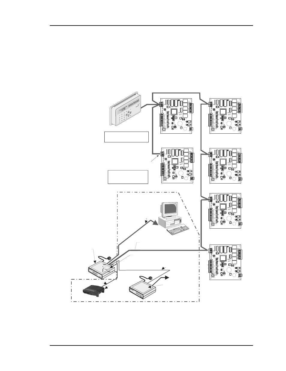
The daisy-chain is the best method for running a communications loop since there is only
one starting point and one ending point for each of the communications loops. See Figure
2-3 and Figure 2-4. The general concept is the same for both the CV and the CV-EX.
Computer
(Optional)
End Of Loop
RS-485
Comm Loop
Loop Start
CV Controller
CV Controller
System Manager
CV Controller
CV Controller
CV Controller
CV Controller
The Comm Loop
Routing Does Not
Have To Follow
The Board Address Sequence
The System Manager Can Be
Connected Anywhere
On The Loop
Optional IP Module
Installs Into CommLink IV
And Provides LAN And Internet
Communications
With The Control System
Ethernet Router
(By Others)
When IP Module
Option Is Used
Optional Remote Link II
Connects to CommLink IV And
Provides Alarm Call-Outs. A
Second Remote Link Is Required If
Connection To Job Site Is Desired
From Remote Computer.
Phone Cable To Telephone
Wall Outlet Jack
Serial Cable To Remote Link
Ethernet Cable To Router
USB Cable To Computer
All Components Shown Inside This Box Are Optional
CommLink IV
The CommLink IV Is Required For
All Systems. The IP Module,
Remote Link II, And Computer Are
Optional On All Systems. All
Computers Require Installation of
Prism Graphical User Interface
Software
9600 Baud
Figure 2-3: CV Communication Loop Wiring, Daisy-Chain Configuration