Operating controls, Ir dome sensor – Audio Enhancement Product Manual User Manual
Page 24
24
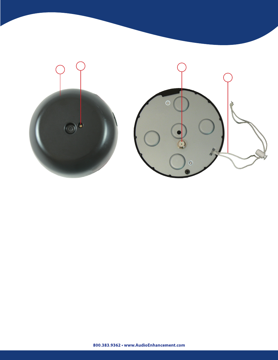
1. Infrared Sensor Cover: Protects sensor and allows IR light to enter . Power supplied by the
receiver .
2. Sensor Connection Terminal: Provides connection to the sensor input terminal of the
infrared wireless receiver via F-connectors and coaxial cable . Power for the sensor is supplied
from the receiver through the coaxial cable .
3. Power Indicator:
• Light is green when the frequency switch is set to [A], 1 and 2 CH .
• Light is orange when the frequency switch is set to [B], 3 and 4 CH .
4. Anchor Strap: Attached to the coaxial cable to prevent the sensor from falling .
Operating Controls
1
3
2
4
IR Dome Sensor
This manual is related to the following products: