1 safe start switch, 2 boot block b select, 1 safe start switch 2.4.1.2 boot block b select – Artesyn MVME7100ET Single Board Computer Installation and Use (June 2014) User Manual
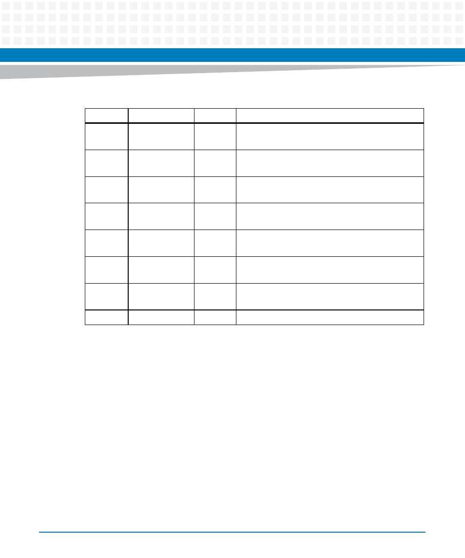
Page 36: Table 2-5, Configuration switch settings (s1), Hardware preparation and installation
Hardware Preparation and Installation
MVME7100ET Single Board Computer Installation and Use (6806800K87E)
36
2.4.1.1
Safe Start Switch
When the SAFE_START switch is OFF, it indicates that the normal ENV setting should be used.
When the switch is set to ON, GEVs, VPD, and SPD settings are ignored and known, safe, values
are used.
2.4.1.2
Boot Block B Select
When the switch is OFF, the flash memory map is normal and block A is selected as shown in
Figure 3. When the switch is ON, block B is mapped to the highest address.
Table 2-5 Configuration Switch Settings (S1)
Switch
Description
Setting
Function
S1-1 Safe
Start
1
[OFF]
ON
Use normal ENV
Use safe ENV
S1-2
Boot Block B
Select
[OFF]
ON
Flash memory map normal and boot block A selected
Boot block B selected, mapped to highest address
S1-3
Flash Bank WP
[OFF]
ON
Entire flash not write-protected
Flash is write-protected
S1-4
JTAG Pass Thru
[OFF]
ON
Normal operation
Pass-Thru mode
S1-5 CORE1
Low
Memory Offset
[OFF]
ON
Normal operation
S1-6
PMC 133 MHz
[OFF]
ON
PMC 100 MHz maximum
PMC 133 MHz maximum
S1-7
Master WP
[OFF]
ON
Master write protect disabled
Master write protect enabled
S1-8
Reserved
1. Switch status is readable from System Status Register 1, bit 5.