3 thermal requirements, 4 thermally significant components, Hardware preparation and installation – Artesyn MVME7100ET Single Board Computer Installation and Use (June 2014) User Manual
Page 29
Hardware Preparation and Installation
MVME7100ET Single Board Computer Installation and Use (6806800K87E)
29
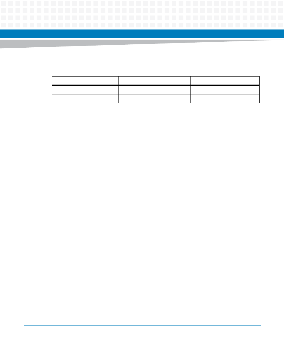
The following table shows the power available when the MVME7100ET is installed in either a 3-
row or 5-row chassis and when PMCs are present.
2.3.3
Thermal Requirements
The MVME7100ET module requires a minimum air flow of 10 CFM uniformly distributed across
the board, with the airflow traveling from the heat sink to the PMC2 site, when operating at a
55°C (131°F) ambient temperature.
2.3.4
Thermally Significant Components
The following table summarizes components that exhibit significant temperature rises. These
are the components that should be monitored in order to assess thermal performance. The
table also supplies the component reference designator and the maximum allowable
operating temperature.
You can find components on the board by their reference designators as shown in
and
. Versions of the board that are not fully populated may not contain some of
these components.
Chassis Type
Available Power
Power With PMCs
3-Row
70 W maximum
Below 70 W
1
1. Keep below power limit. Cooling limitations must be considered.
5-Row
90 W maximum
Below 90 W
1