Table 2-2, Critical temperature spots for comx-core series, Figure 2-4 – Artesyn COMX-CORE Series Installation and Use (August 2014) User Manual
Page 33: Air requirement to cool bottom side memory, Hardware preparation and installation
Hardware Preparation and Installation
COMX-CORE Series Installation and Use (6806800K11F)
33
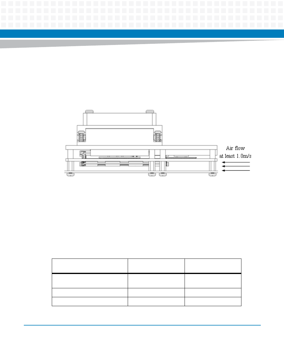
If a memory is placed at the bottom, the system should provide at least 1.0m/s air flow into the
gap between COMX-CORE Series and the carrier board (illustrated in the figure below) to keep
the surface temperature of the memory within 95 °C, otherwise, the function of this memory
is not guaranteed.
To keep the optimized cooling capability, it is not recommended to remove a used cooler (or
heat spreader) from one COMX-CORE Series module and install it on another module without
replacing thermal pads with new ones.
The following table summarizes components that exhibit significant temperature rises and
their maximum allowable operating temperature. These components should be monitored in
order to assess thermal performance.
Figure 2-4
Air Requirement to Cool Bottom Side Memory
Table 2-2 Critical Temperature Spots for COMX-CORE Series
Component Identifier
Heat Dissipation Power
(W)
Maximum Allowable
Temperature (°C)
CPU-P4505/520E/620LE/620UE
35/35/25/18
CPU: 105 (Tj)
GMCH: 100 (Tj)
PCH-QM57/HM55
3.5/3.5
108 (Tj)
2 X DDR3 SO-DIMM 1GB/2GB/4GB
1.5/3/3.5
95 (Tc)