Remote control signals -5, Figure 5-2. external control connector -5, 2 remote control signals – AMETEK CW-M User Manual
Page 45
Elgar CW-M Series
M161570-01
5-5
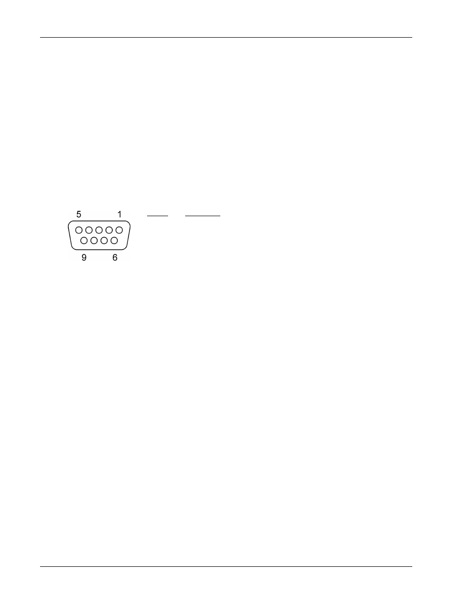
5.2 REMOTE CONTROL SIGNALS
A nine-
pin ‘D’ connector on the rear panel, marked EXT CONTROL,
provides for the application of DC voltage signals to control both the
voltage amplitude and frequency of the power supply’s output signal.
A 0V
–5V signal has full scale control over either function. The effect of the
external analog control signal is additive with the setting of the function’s
front panel control setting. The combined effect is full scale limited. The
impedance of the external analog control inputs is 10k ohms, nominal.
Connect the voltage control signal to pin 1. Connect the frequency control
signal
to
pin 2. Pin 3 is the common return for all signals. See Figure 5-2.
Pin #
Function
1
Analog voltage programming 0 to 5 VDC full scale
2
Analog frequency programming 0 to 5 VDC full scale
3
Analog ground common return for all signals
4
–9
Reserved for future expansion
Figure 5-2. External Control Connector
Note:
When programming voltage through the EXT CONTROL
connector, the analog frequency programming signal, if not used, must be
tied to analog ground. When programming frequency through the EXT
CONTROL connector, the analog voltage programming signal, if not used,
must be tied to analog ground.
Failure to do so will not harm the unit, but changing either the programmed
voltage or frequency would alter the programmed value of the other.
On Pin 3, analog ground common must be held within 5 V DC of chassis.