Gpio and parport information, Gpio pinout, Gpio – Adtec digital EN-91 / EN-91P (version 1.02.29) Manual User Manual
Page 37: Parport, Information, Pinout, Ethernet, Access
GPIO and Parport information
The GPIO port allows encoder stop / start control and TTL voltage output for
monitoring systems. TTL pin behavior by default is HI (3V) when encoding and LO (0V)
when not encoding. Logic of the TTL pin can be configured based upon video detection,
encode status, and manual override with the PP9 API command. Please view API details for
further configuration information.
The DVC Parport allows custom events to be programmed upon input pin voltage
change. It contains 4 available inputs for custom commands. Please contact technical
support for advanced usage in programming the parallel port.
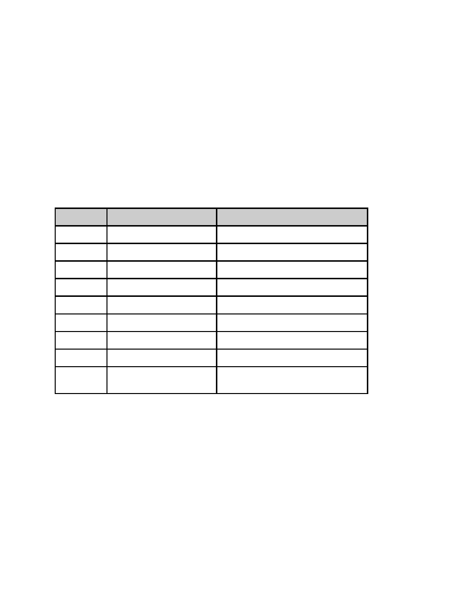
GPIO Pinout
PIN
Designation
Function
1
NC
No Connect
2
D3
reserved for future functionality
3
D2
RECORD ( start encoder ) ( input )
4
D1
STOP ( stop encoder ) ( input )
5
D0
reserved for future functionality
6
NC
No Connect
7
5VDC
+5V DC
8
GND
ground
9
TTL Tally
HI (3V) or LO(0V) based upon PP9
logic ( output )
- EN-100 (version 2.00.31) Manual signEdje (version 02.07.09) Quick Start mediaHUB-HD 422 (version 1.01.10_M_2) Quick Start mediaHUB-HD Pro (version 03.07.19) Quick Start YUV2QAM (version 01.02.01) Quick Start EN-30 (version 1.02.02) Quick Start EN-81 (version 2.02.28) Manual EN-80 (version 2.02.28) Manual