Delta 20-330 User Manual
Page 9
9 - English
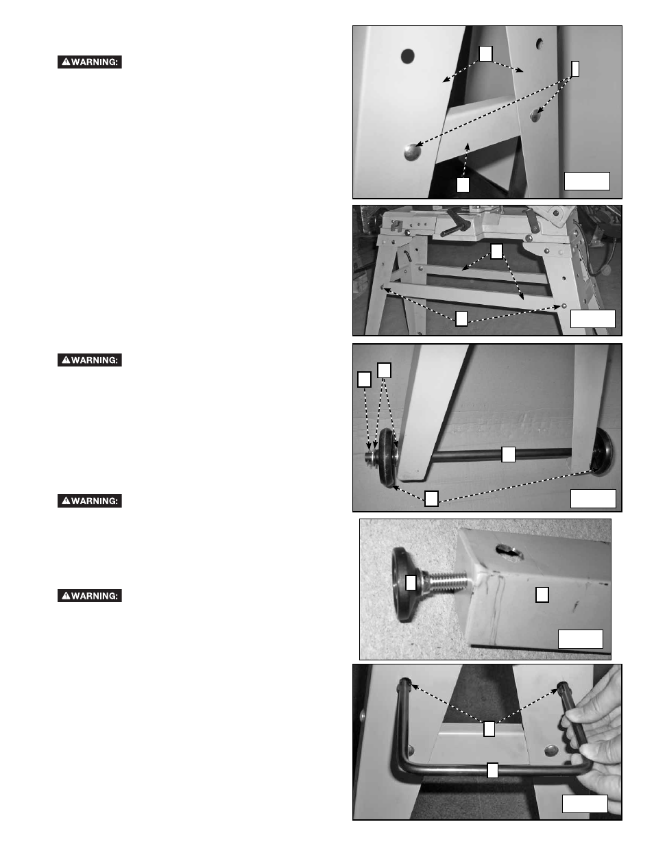
MOUNTING BRACKETS
ONTO STAND LEGS
Disconnect machine from power source.
To assemble the two short brackets, one of which is
shown at (G) Fig. 6, to the four band saw legs, two of
which are shown at (H), use four 5/16"-1/2" carriage
bolts (two of which are shown at (I) Fig. 4), four 5/16"
flat washers and four 5/16" hex nuts. To assemble, align
the holes in the bracket with the holes in the legs. Then,
insert a 5/16"-1/2" carriage bolt through the hole in the
bracket and the hole in the leg, place a 5/16" flat washer
onto the screw and thread a 5/16" hex nut onto the
screw and tighten securely. Repeat this process for the
three remaining holes.
To assemble the two long brackets (J) Fig. 7 to the band
saw legs, you will use four 5/16"-1/2" carriage bolts
(two of which are shown at (K)), four 5/16" flat washers
and four 5/16" hex nuts. Align the holes in the brackets
with the holes in the legs as shown in Fig. 8 and attach
at all four holes using the hardware mentioned. Insert
the carriage bolt through the leg and then through the
bracket. Then place a washer on the bolt and secure the
assembly with a hex nut.
ASSEMBLING WHEELS
Disconnect machine from power source.
Assemble the wheels (L) Fig. 8, to the bottom of the
right side (below the motor). To assemble, insert the
wheel shaft (M) through the holes of the right side legs
as shown in Fig 5. First, place a 5/8" flat washer (N) onto
the wheel shaft. Then place the wheel (L) onto the wheel
shaft, followed by the other 5/8" flat washer (N). Fasten
in place using the two supplied cotter pins (O). Repeat
this process for the other wheel on the other leg.
MOUNT RUBBER FEET ONTO LEFT LEGS
Disconnect machine from power source.
To assemble the two rubber feet, one of which is shown
at (P) Fig. 9, to the left side legs, thread the stud screw
on the foot until it stops on the bottom of the leg (Q).
Repeat this process for the other side.
ASSEMBLING STAND HANDLE
Disconnect machine from power source.
Install the stand handle (R) Fig. 10, into two holes in the
legs on the left side of the band saw (the side opposite
the motor). As shown in Fig. 10, insert ends of handle
into the two holes (S) and fasten in place underneath
the saw using the two cotter pins supplied (not shown).
Insert the cotter pins through the holes in the stand
handles and bend each end of the pin back onto the
handle.
Fig. 6
Fig. 7
Fig. 8
Fig. 9
Fig. 10
G
H
I
J
K
N
L
M
O
P
Q
R
S