Delta 20-330 User Manual
Page 12
12 - English
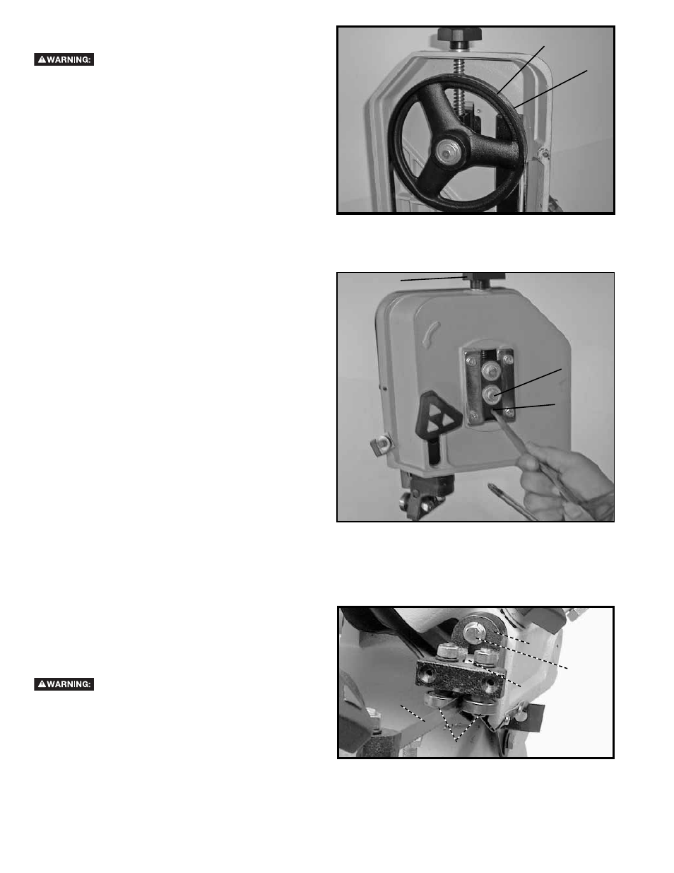
ADJUSTING BLADE TRACKING
Disconnect machine from power source.
1. Place the saw arm in the vertical position and open
the wheel cover.
2. Turn on the band saw. The blade is tracking
properly when the back of the blade (B) Fig. 17, is
just touching the edge of the wheel flange (C). The
back of the blade should not be rubbing against the
flange.
3. If an adjustment is necessary the blade guide
bearings and blade support bearings (J) Fig. 19 (two
of which are shown) should be clear of the blade.
4. Loosen screw (D) Fig. 18.
5. With the band saw running, turn adjusting screw (E)
until the blade is tracking properly making certain
blade tension is maintained by turning blade tension
knob. (F). The blade is tracking properly when the
back side of the saw blade just touches the flange
on the wheel.
6. Tighten screw (D) Fig. 18, when adjustment is
complete.
7. IMPORTANT: IT IS POSSIBLE WHEN MAKING
THIS ADJUSTMENT TO OVER TIGHTEN THE
ADJUSTING SCREW (E), FIG. 18, AND CAUSE
THE BLADE TO BE MISALIGNED. If this happens,
loosen the adjusting screw (E) several turns but do
not remove it from its threaded hole and loosen
screw (D). Turn screw (D) clock-wise until it stops
but do not tighten. Then turn the adjusting screw (E)
clockwise until it bottoms. Turn on the machine and
turn adjusting screw (E) clockwise a small amount
at a time until the blade is tracking correctly and
tighten screw (D) Fig. 18.
8. After the blade is tracking properly make sure to
ad-just the blade guide bearings and blade support
bearings.
Fig. 17
Fig. 18
ADJUSTING BLADE SUPPORT BEARINGS
Disconnect machine from power source.
1. The blade support bearing (F) Fig. 19, should be
adjusted so it just touches the back of the saw
blade after the blade is tracking properly. To adjust,
loosen screw (G) and move the bracket (H) up or
down until the support bearing (F) just touches the
back of the blade (I). Then tighten screw (G).
2. Adjust the other blade support bearing in the same
manner.
Fig. 19
D
E
F
H
G
F
I
J
B
C