Operation, Operational controls and adjustments – Delta 20-330 User Manual
Page 11
11 - English
Fig. 13
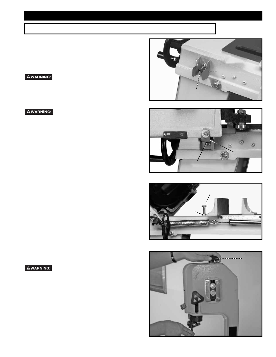
AUTOMATIC SHUT-OFF
When the band saw is in the horizontal position, the saw
should shut itself off automatically. After a completed
cut has been made, and the saw is in the down or
horizontal position, the shut-off bracket (B) Fig. 14 will
contact the toggle switch (A) and push it to the down
position, turning off the power. IMPORTANT: THE
SHUT-OFF BRACKET (B) SHOULD NOT REST ON
OR BE SUPPORTED BY THE TOGGLE SWITCH (A).
The downward travel of the saw should be adjusted
to just trip the toggle switch at its lowest position. To
adjust the downward travel of the saw arm, loosen lock
nut (C) Fig. 15, and turn the stop screw (D) in or out
until the correct adjustment is made; then tighten lock
nut (C).
Fig. 14
Fig. 15
ADJUSTING BLADE TENSION
Disconnect machine from power source.
Turn blade tension handwheel (A) Fig. 16, clockwise
to increase or counterclockwise to decrease blade
tension. Correct tension is obtained when the blade is
just tight enough that no slippage occurs between the
blade and the wheels.
When the machine is not in use, release the blade
tension.
Fig. 16
B
A
D
C
A
B
B
OPERATION
OPERATIONAL CONTROLS AND ADJUSTMENTS
STARTING AND STOPPING MACHINE
1. The on/off switch (A) Fig. 13 is located on the front
of the band saw. To turn the machine "ON, move the
switch up to the "ON" position.
2. To turn the machine "OFF", move the switch (A)
down to the "OFF" position.
Make sure that the switch is in the
"OFF" position before plugging cord into outlet. Do
not touch the plug’s metal prongs when unplugging
or plugging in the cord.
LOCKING SWITCH IN "OFF" POSITION
In the event of a power outage (such
as a breaker or fuse trip), always move the switch to
the "OFF" position until the main power is restored.
IMPORTANT: When the machine is not in use, the
switch should be locked
in the "OFF" position to prevent
unauthorized use,
using a padlock with a 3/16" diameter
shackle through the holes at (B) FIg. 13.
A