Water pump wiring, Water pump wiring -1 – Paxton Superchargers Denali User Manual
Page 53
19-1
P/N: 4809639
©2004 Paxton Automotive
All Rights Reserved, Intl. Copr. Secured
12APR04 v3.0(01-03Denali/Esc(4809639v3.0))
Section 19
WATER PUMP WIRING
19.
WATER PUMP WIRING
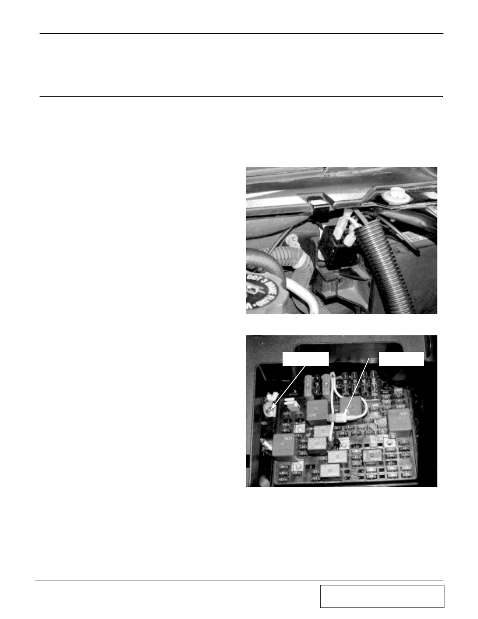
A.1 Escalade/Denali: Mount the supplied
water pump relay on the fire wall located
to the right of the FMU bracket. (See Fig.
19-a.)
A.2 H2 Hummer: Mount the supplied water
pump relay on the lower plastic area of the
power distribution block next to the fuel
pump relay. (See Fig. 11-f.)
B.
Connect the red 12-gauge wire from termi-
nal #30 to the supplied fuse holder using
the supplied butt connector. Install a yel-
low ring terminal on the other end of the
fuse holder and bolt to the fuse box power
supply. (See Fig. 19-b.)
C.
Feed the yellow wire from relay terminal
#85 to the fuse box (electrical center) on
the driver’s side of the engine bay. Route
the wire to the yellow wire from the fuel
pump relay. Tap into the line using the
supplied “T” splice connector. (See Fig.
19-b.)
D.
Run the black wire from terminal #86 on
the fuel pump relay to ground.
E.1 Escalade/Denali: With the long red 12-
gauge wire connected to the water pump
relay terminal #87, route the free end
down along the fenderwell and under the
base of the radiator over to the positive
(blue/green) wire on the water pump.
(Remove the wiring connector on the
water pump before extending the wires.)
Secure as necessary to avoid heat and
sharp edges.
E.2 H2 Hummer: With the long red 12-gauge
wire connected to the water pump relay
terminal #87, route the free end down the
fenderwell to the positive (blue/green) wire
on the water pump. (Remove the wiring
connector on the water pump before
extending the wires.) Secure as necessary
to avoid heat and sharp edges.
F.
Run the negative (brown) wire from the
water pump to a clean ground.
G.
With the key on, make sure the charge
cooler water pump is operating and that
water is flowing through the surge tank.
Fill the surge tank if necessary. If the water
is not flowing, remove the charge cooler
supply hose and lower until water flows
out of the hose. If necessary, provide light
Fig. 19-a
Fig. 19-b
TAP INTO FUEL
PUMP WIRE
FUSE BOX
POWER SUPPLY
suction to the hose to help prime the
pump. Verify water flow. Do not let the
pump run for extended periods (30 seconds
or more) without water flow. Fill the
charge cooler tank until the level stabilizes.