Paxton Superchargers Denali User Manual
Page 39
12-3
P/N: 4809639
©2004 Paxton Automotive
All Rights Reserved, Intl. Copr. Secured
12APR04 v3.0(01-03Denali/Esc(4809639v3.0))
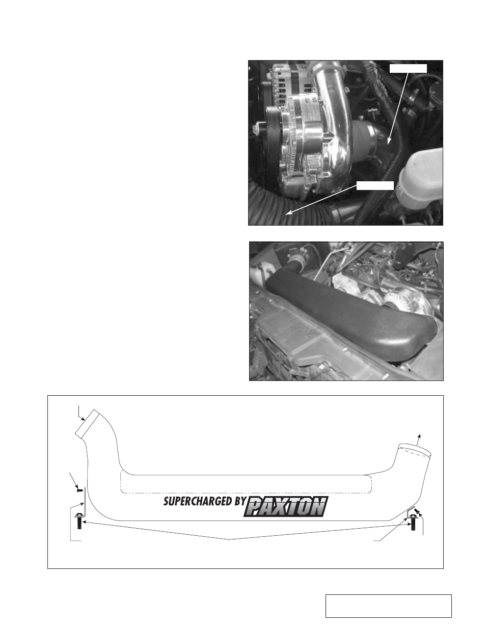
12.C H2 HUMMER INLET DUCT INSTALLATION
A.
Install the supplied 3-1/2" x 3" sleeve onto
the MAF outlet, and the 3-1/2" x 2" sleeve
on the inlet of the supercharger.
B.
Reinstall the upper fan shroud. Remove
the two screws securing the top of the radi-
ator to the core support.
C.
Slide the entry of the large plastic inlet
duct into the sleeve installed on the MAF.
Lower the inlet duct onto the top of the
radiator shroud.
D.
Reinstall the factory radiator bolts through
the two supplied inlet duct mounting tabs
and into their original bolt holes.
E.
Insert the 1/4"-20 x 1/2" screws through
the brackets and onto each side of the inlet
duct using the supplied washers. Tighten
the screws. (See Fig 12.B-f.)
F.
Install the supplied 180° inlet duct onto the
inlet of the supercharger. Orient the duct so
that there is equal space between, the ECM
and the master cylinder. (See Fig. 12.B-g.)
G.
Install the supplied #52 hose clamps and
3-1/2" x 13" long flex hose between the
180° cast duct and the rotomold duct.
H.
Using the supplied 3/8" hose mender, con-
nect the supplied 3/8" hose from the 3/8"
fitting on the inlet duct to the passenger’s
side valve cover breather hose. Secure the
hose so that it cannot interfere with the
throttle arm or cable. (See Fig. 12.B-c.)
I.
Install and tighten the hose clamps on each
connection.
FACTORY RADIATOR SCREWS
SUPPLIED
1/4-20 x .50
SCREW
TO FACTORY AIR BOX
SUPPLIED
1/4-20 x .50
SCREW
ATTACH TO 3.5" FLEX HOSE
WHICH LEADS TO CAST
INLET DUCT
DRIVER’S
SIDE BRACKET
PASSENGER’S
SIDE BRACKET
Fig. 12
.B
-f
Fig. 12
.B
-g
Fig. 12
.B
-h
TOP VIEW
H2 HUMMER INLET
180° INLET
FLEX HOSE