A fuel pump wiring and in, B fuel pump wiring and in, Fuel pump wiring and installation (2003 hummer) -1 – Paxton Superchargers Denali User Manual
Page 33: Fuel pump wiring and installation
11-1
P/N: 4809639
©2004 Paxton Automotive
All Rights Reserved, Intl. Copr. Secured
12APR04 v3.0(01-03Denali/Esc(4809639v3.0))
Section 11
FUEL PUMP WIRING AND INSTALLATION
11.A FUEL PUMP WIRING AND INSTALLATION (Escalade/Denali)
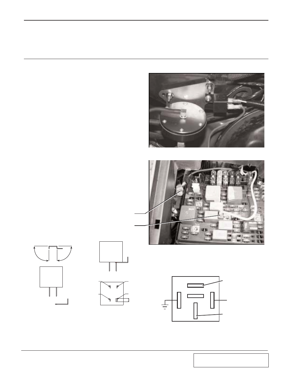
A.
Mount the supplied fuel pump relay on the
fire wall located to the right of the FMU
bracket. (See Fig. 11
.A
-a.)
B.
Connect the red 12-gauge wire from termi-
nal #30 to the supplied fuse holder using
the supplied butt connector. Install a yel-
low ring terminal on the other end of the
fuse holder and bolt to the fuse box power
supply terminal as shown in Fig. 11
.A
-b. In
order to reach the terminals, the fuse box
cover must be unsnapped from the base
and raised for access. (See Fig. 11
.A
-b.)
C.
Feed the yellow wire from relay terminal
#85 to the fuse box (electrical center).
Route the wire to the stock fuel pump
relay and connect using the supplied fuse
tap. Bend the fuse tap as shown in Fig.
11
.A
-c.
D.
Run the black wire from terminal #86 on
the fuel pump relay to ground.
E.
With the long red 12-gauge wire connected
to the fuel pump relay terminal #87, route
the free end down to the area near the fuel
filter on the driver’s side inner frame rail
under the door. Secure as necessary to
avoid heat and sharp edges.
Fig. 11.A-a
Fig. 11.A-b
RED WIRE FROM PAXTON SUPPLIED
RELAY TERMINAL #30 ATTACHES HERE
YELLOW WIRE FROM PAXTON SUPPLIED
RELAY TERMINAL #85 ATTACHES HERE
86
IGNITION
RELAY
SIDE VIEW
85
87
30
FUSE TAP
MODIFICATION
BEND UP 90
°
BEND UP 90
°
IGNITION
RELAY
MODIFIED
FUSE TAP
INSTALLED MODIFIED
FUSE TAP
BOTTOM VIEW
Fig. 11.A-c
RELAY
87
87A
86
85
30
(+) BATTERY
TERMINAL
(+) TERMINAL
ON T-REX
FUEL PUMP
GROUND
PAXTON SUPPLIED
FUEL PUMP
TO MODIFIED FUSE
TAP ON FACTORY FUEL
PUMP RELAY
Fig. 11.A-d