Input signal processing, 2 connecting speakers – KLING & FREITAG K&F TOPAS User Manual
Page 23
User's manual
System Amplifier K&F TOPAS
KLING & FREITAG GMBH © 2014
Version 3.1
Page 23 of 65
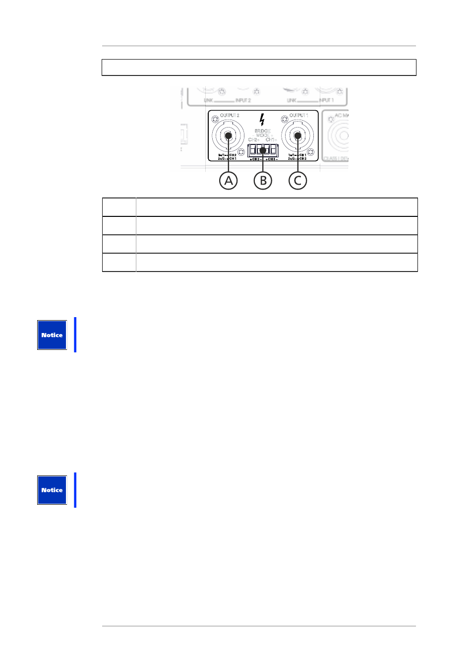
5.5.2
Connecting Speakers
Position
Description
A
Speakon connector, CH2 = 1+/1-, CH1 = 2+/2-
B
Phoenix connector, CH 2 and CH 1
C
Speakon connector, CH1 = 1+/1-, CH2 = 2+/2-
The speaker outputs are designed as Speakon and Phoenix connectors. Both outputs are
available on both Speakon connectors.
All outputs of a channel are electrically connected to one another in parallel.
On each channel of the amplifier, you can operate a load with an impedance of at least 2
ohms each.
In addition to two-channel mode (Dual/Mono), the amplifier can also be switched to so-called
bridge mode (Bridge). Each operating mode requires a different type of speaker connection.
Bridge mode
In the bridge mode, both amplifier channels are bundled to one channel. In that case the
amplifier is capable of providing very high output power levels.
To operate a speaker in bridge mode,
•
the speaker must be connected between CH1+ and CH2+ [compare to illus. LS Outputs].
In this case, CH1+ is connected to the positive pin of the speaker.
•
the amplifier routing must be switched to 'Bridge Mode'. (see page 31)
Never allow the load impedance to fall below 4 ohms in bridge mode. Otherwise, the
amplifier would interpret this to be a short circuit and would shut down early.
The filter settings for channel 2 are inactive.
In the web interface, switching is possible in the menu item. (see page 31)