DekTec DTM-3200 IP-ASI Converter User Manual
Page 42
DTM-3200 – OEM Ethernet TSoIP Converter
User Manual
42
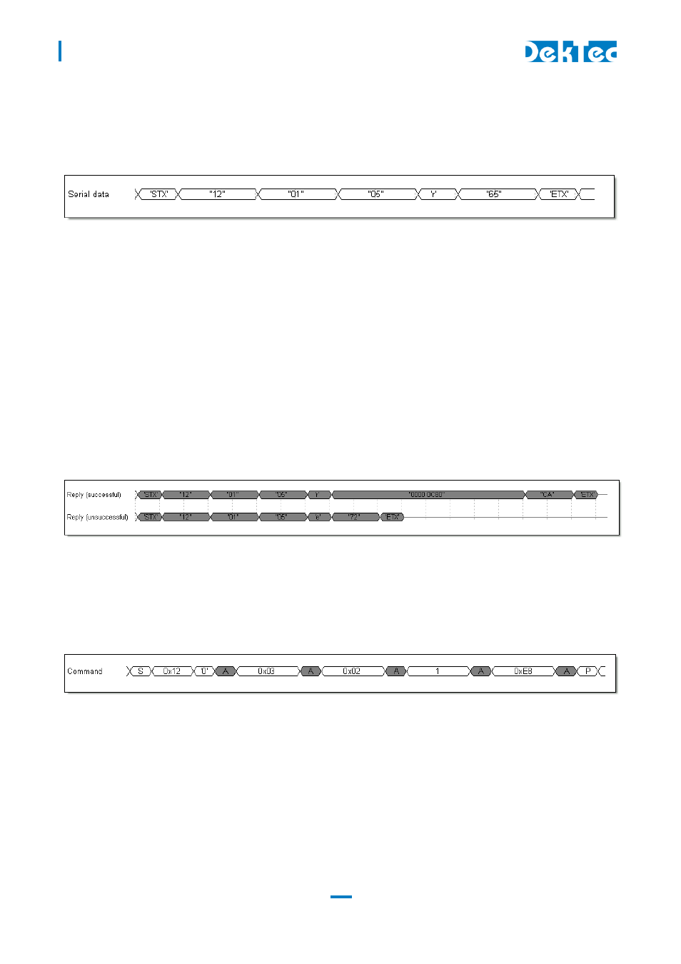
Serial read command
Figure 10 shows the read command of the device type number (category 1, setting 5, no index). An
index is not required for this category and the returned data consists of 4 bytes (int32). All values are
displayed as ASCII characters.
Figure 10: Read-command for the device type setting
The command consists of the following parts:
Start character ‘STX’
Two hexadecimal address characters (“12”)
Two hexadecimal category characters (“01”)
Two hexadecimal setting characters (“05”)
A read character ‘R’
Two hexadecimal checksum characters (“85”)
End character ‘ETX’
Figure 11 shows the two possible replies from the command in Figure 10. The replies are similar to
the commands with the exception of the data-characters or the read character. On a successful
command, the reply-data is set to the corresponding data (0x00000C80). When the received
command cannot be executed, the read character is set to the ASCII character ‘E’. In both cases the
checksum is also updated.
Figure 11: Reply after a device type read-command
I
2
C read command
Figure 12 shows the communication sequence used to issue a read subnet mask command
(category 3, setting 2, no index). An index is not required for this category and the returned data
consists of an IP-address.
Figure 12: Send subnet-mask read-command
The command consists of the following bytes:
Address and I
2
C write-bit (0x12 and ‘0’)
Category byte (0x03)
Setting byte (0x02)
Read byte (0x01)
Checksum (0xE8, see Table 2). The checksum is computed with the address and without the
I
2
C write-bit.