3 order codes 3.4 hardware installation, 1 mechanical installation, 2 asi connector – DekTec DTM-3200 IP-ASI Converter User Manual
Page 14: 3 parallel-ts connector
DTM-3200 – OEM Ethernet TSoIP Converter
User Manual
14
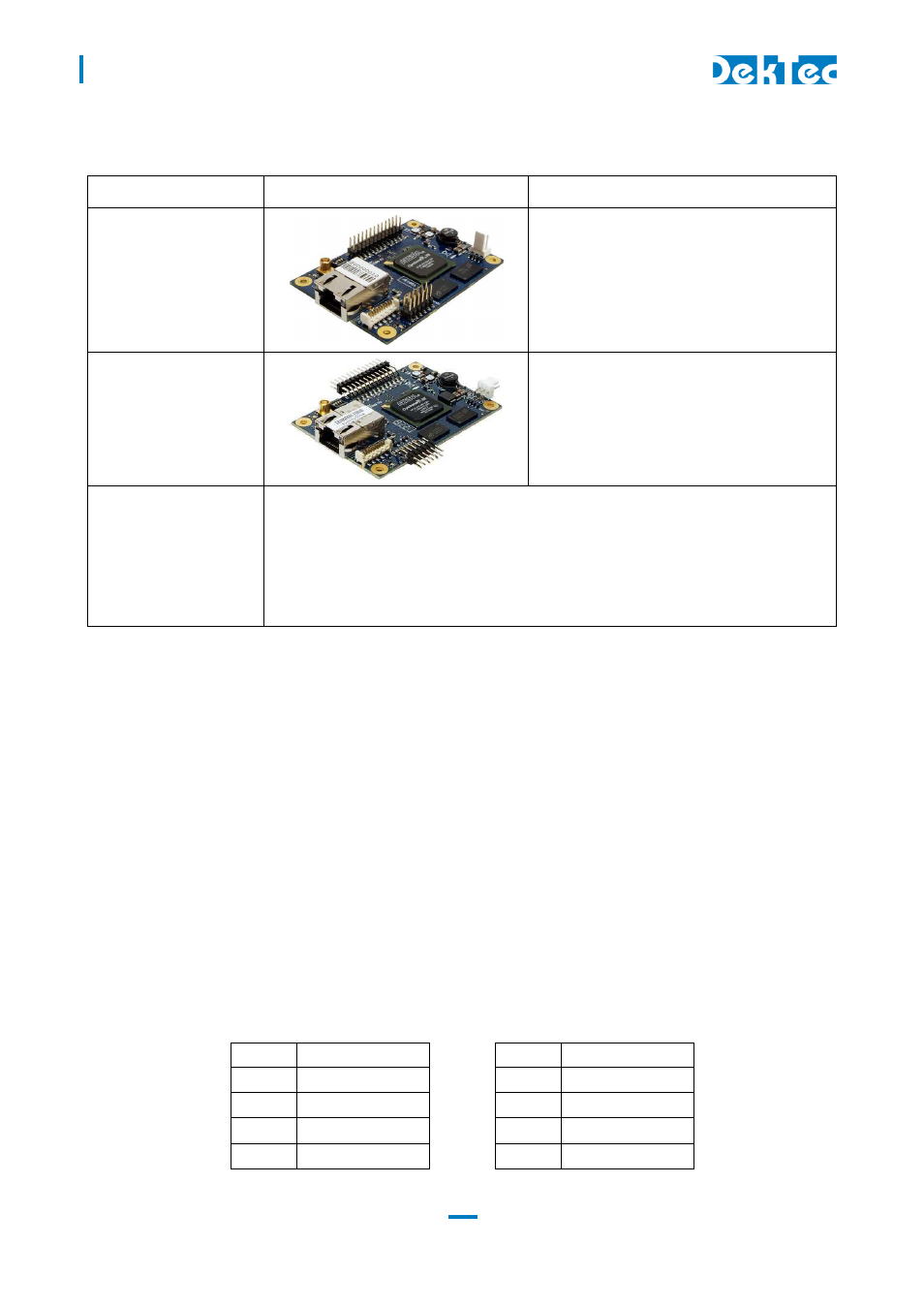
3.3 Order codes
Order Code
Picture
Description
DTM-3200
Model with standard pin headers
Note
: The photo shows a power connector
with straight pins, but on current production
a right-angle power connector is used, like
on DTM-3200-RA
DTM-3200-RA
Model with right-angle pin headers
DTM-3200-DEVKIT
The DTM-3200 development kit contains the following items:
DTM-3200 placed on four plastic studs
DTM-3200-USB-INTERFACE board
10V/1.2A power supply
USB cable type A to mini B
MCX to BNC cable assembly with a length of 130 mm
3.4 Hardware installation
3.4.1 Mechanical installation
The unit can be mounted onto a support plate by means of four 2.5 mm bolts and appropriate
spacers. Ensure that there is sufficient airflow to provide cooling of the board.
3.4.2 ASI connector
The ASI connector (1) is an MCX connector with an impedance of 75 ohm.
3.4.3 Parallel-TS connector
The pinning of the parallel Transport-Stream connector (2) is displayed in the table below. The
signal levels and pin numbering the same as DVB-SPI.
Warning: Although the pinning is the same, the parallel interface is not compatible with DVB-SPI,
because the clock of the DTM-3200’s parallel interface is fixed to 27MHz (in DVB-SPI the clock is the
TS rate in byte/sec).
Pin
Signal
Pin
Signal
1
DCLK+
2
DCLK-
3
GND
4
GND
5
D7+
6
D7-
7
D6+
8
D6-