Appendix b. dtm-3200 development kit – DekTec DTM-3200 IP-ASI Converter User Manual
Page 37
DTM-3200 – OEM Ethernet TSoIP Converter
User Manual
37
Appendix B. DTM-3200 Development Kit
B.1 DTM-3200 development kit – Contents
The DTM-3200 development kit contains the following items:
DTM-3200 placed on four plastic studs
DTM-3301 USB-interface board
10V/1.2A power supply
USB cable type A to mini B
MCX to BNC cable assembly (length = 130mm)
DekTec USB flash drive containing DTM-3200 documentation and development tools (as well
as documentation on DekTec’s other products)
The development kit can be ordered from DekTec using type number DTM-3200-DEVKIT.
B.2 Using the DTM-3200 development kit
B.2.1 DIP switch setting
Before using the DTM-3200 it is essential to set the DIP switches on the DTM-3200 PCB into the right
position. The required settings of the DIP switches are shown in the table below. For a description of
the purpose of the individual DIP switches, refer to §3.4.4.
DIP switch
Setting
Description
1,2
off, off
Sets DTM-3200 address to 0x40
3
off
Selects RS-232 communication for control
4
on
Selects a baud rate of 115.2kBd
These DIP switch settings become active only after a system reboot.
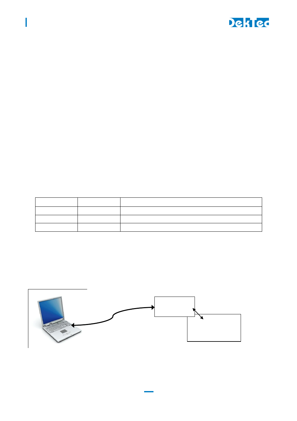
B.2.2 Hardware installation
The DTM-3301 USB-interface board has to be plugged on the Control pin-header of the
DTM-3200. The pin-1 indication of the DTM-3301 should match the pin-1 indication of the
DTM-3200.
Connect the DTM-3200 to the power-supply using the power connector (see §3.2.7). The DTM-3200
will boot which will take a few seconds. During this time the two LEDs on the DTM-3200 are flashing
in a start-up pattern. Wait until the DTM-3200 status LED turns green.
DTM-3200
DTM-3301
USB-interface
USB cable
control
interface