4 dip switches – DekTec DTM-3200 IP-ASI Converter User Manual
Page 15
DTM-3200 – OEM Ethernet TSoIP Converter
User Manual
15
9
D5+
10
D5-
11
D4+
12
D4-
13
D3+
14
D3-
15
D2+
16
D2-
17
D1+
18
D1-
19
D0+
20
D0-
21
DVALID+
22
DVALID-
23
PSYNC+
24
PSYNC-
25
GND
26
GND
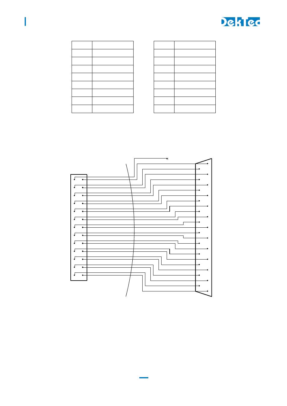
The pin assignment of the pin header has been chosen in such a way that a flatcable with a sub-D
male flatcable connector (25-way sub-D; ISO 2110) at the other end can be connected directly to
the board.
26-pin female header flatcable 25-pin male sub-D
3.4.4 DIP switches
The DIP switches permit configuration of I
2
C device address, RS-232 or RS-485/422 mode and the
baud rate. The state of the DIP switches is read at power up only. Changing the DIP switch settings
while power is on has no effect.
25
24
23
22
21
20
19
18
17
16
15
14
13
12
11
10
9
8
7
6
5
4
3
2
1
26
24
22
20
18
16
14
12
10
8
6
4
2
25
23
21
19
17
15
13
11
9
7
5
3
1
NC