Measuring non-continuous data – Dataman 520 Series User Manual
Page 31
DATAMAN 520 series oscilloscope with rollmode
User’s Guide
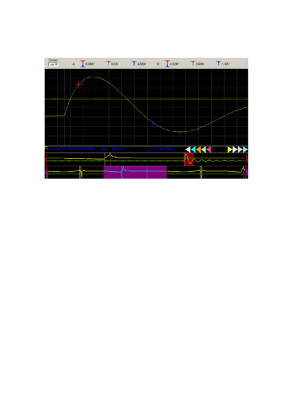
the main screen, its position is marked by left or right pointing triangle. The color of
the triangle is the same as the color of the cursor.
Fig. 5.3.1.7. – Viewer screens with waveform cursors and time synchro mark
The relative position (order) of these triangles is the same as the placement of the
cursors.
Positioning the mouse cursor to the triangle, the real time of the cursor position and
the time period between the red screen cursor and the selected waveform cursor (or
synchronization time mark) is displayed. If the waveform cursor is visible on the main
screen, positioning the mouse cursor to it has the same effect as the positioning to the
triangle. If the screen cursors are not active, the time period between the waveform
cursor and the red screen cursor is not displayed.
The triangles are also usable to change the main screen position in the waveform.
Clicking to triangle changes the position of the main screen to display waveform
around the selected cursor (or time synchronization mark).
The screen cursors are also usable to measure voltages. The voltage of the vertical
position of red cursor, blue cursor and voltage between red and blue cursors (for
channels A and B) are displayed above the screen.
5.3.2. Measuring non-continuous data
Two types of discontinuity can occur:
- Internal buffer overflow during data acquisition.
- Discontinuity caused by ARM-ing data acquisition.
- 31 -