CIRCUTOR RGU2 Series User Manual
Page 15
5.5.- OUTPUTS
The unit has two independent output relays:
5�5�1� TRIP RELAY, TRIP
Switched contact relay (terminals 13, 14 and 15 in
)
The unit can be programmed to modify the logical status of the contact (
refer to section 5.6.3)
from the standard NC/NO status to the NO/NC positive safety status.
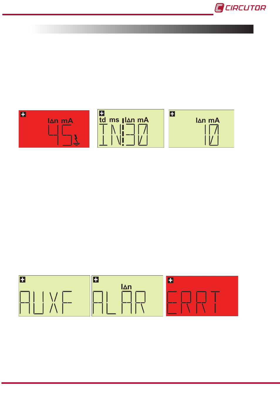
The positive safety status is shown on all screens that refer to the
TRIP, with the + sign (
). The prealarm/fault screen will not be affected by this.
Figure 14: Positive safety status screen
5�5�2� AUXILIARY RELAY, AUX
Simple contact relay (terminals 4 and 5, and
Figure 1) non-interlocking. Its operation can be
programmed as a prealarm or fault relay (
refer to section 5.6.2 )
Prealarm (ALAR), activated when the IΔ > 0.5•IΔn, in 200 milliseconds. The logical sta-
tus of the contact (
refer to section 5.6.3) can be changed from the NO standard status to the
NC positive safety status.
The Fault relay (AUXF), is a
ctivated to notify fault events in the unit, such as:
undervoltages (the voltage is below the unit's operation voltage - the unit turns off below this
voltage) or faults in the external sensor.
In this case, the relay operates with the positive safety status.
Positive safety is shown with the + sign (only in the screens that refer to the AUX relay).
Figure 15:Screens with a positive safety status�
15
Instruction Manual
RGU-2 Earth Leakage Relay