Fireplace installation – Dimplex BLF50 User Manual
Page 11
11
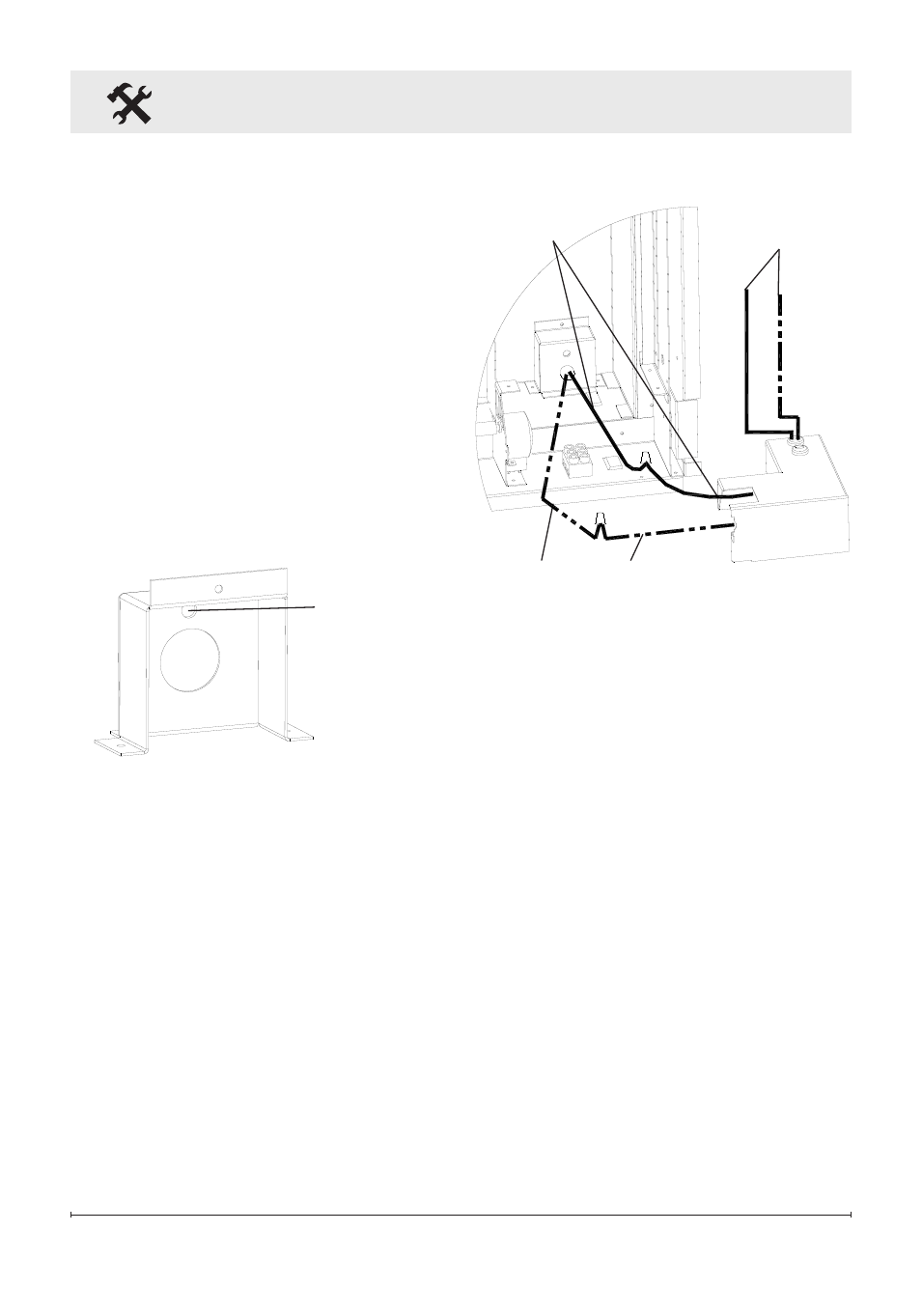
Figure 7
Fireplace Installation
screws which hold the
junction box to the fireplace
chassis (Figure 6).
Pull the junction box and
8.
power cord out the front of the
fireplace.
replace removed junction
9.
box cover with the supplied
hard-wire cover replacement
(Figure 7) and install using
screws removed in steps 6
Figure 8
Wires to
controls
black live
wires
White neutral wires
white wire from the power
supply using the second wire
connector from step 5 (Figure
8).
Attach green grounding wire
13.
to hard wire cover cover with
provided grounding screw.
Place wire in-between screw
and lock washer and tighten.
reposition the electrical box
14.
cover over the wires and
connectors and attach to
fireplace chassis using the
screw removed in step 3.
Carefully reinsert partially
15.
reflective glass into fireplace
and anchor in place using
glass brackets and screws
removed in step 1.
and 7.
Leaving a minimum of 3" (7.6
10.
cm) of slack, route the power
supply through the hole in the
alternate junction box cover
and secure with a wire clamp
(not supplied).
Connect the black wire (live)
11.
from the unit to the black wire
from the power supply using
one of the wire connectors
removed in step 5 (Figure 8).
Connect the white wire
12.
(neutral) from the unit to the
Hole for
Ground screw