Output options, Output data width, Output options -4 – Altera CIC MegaCore Function User Manual
Page 20: Output data width -4
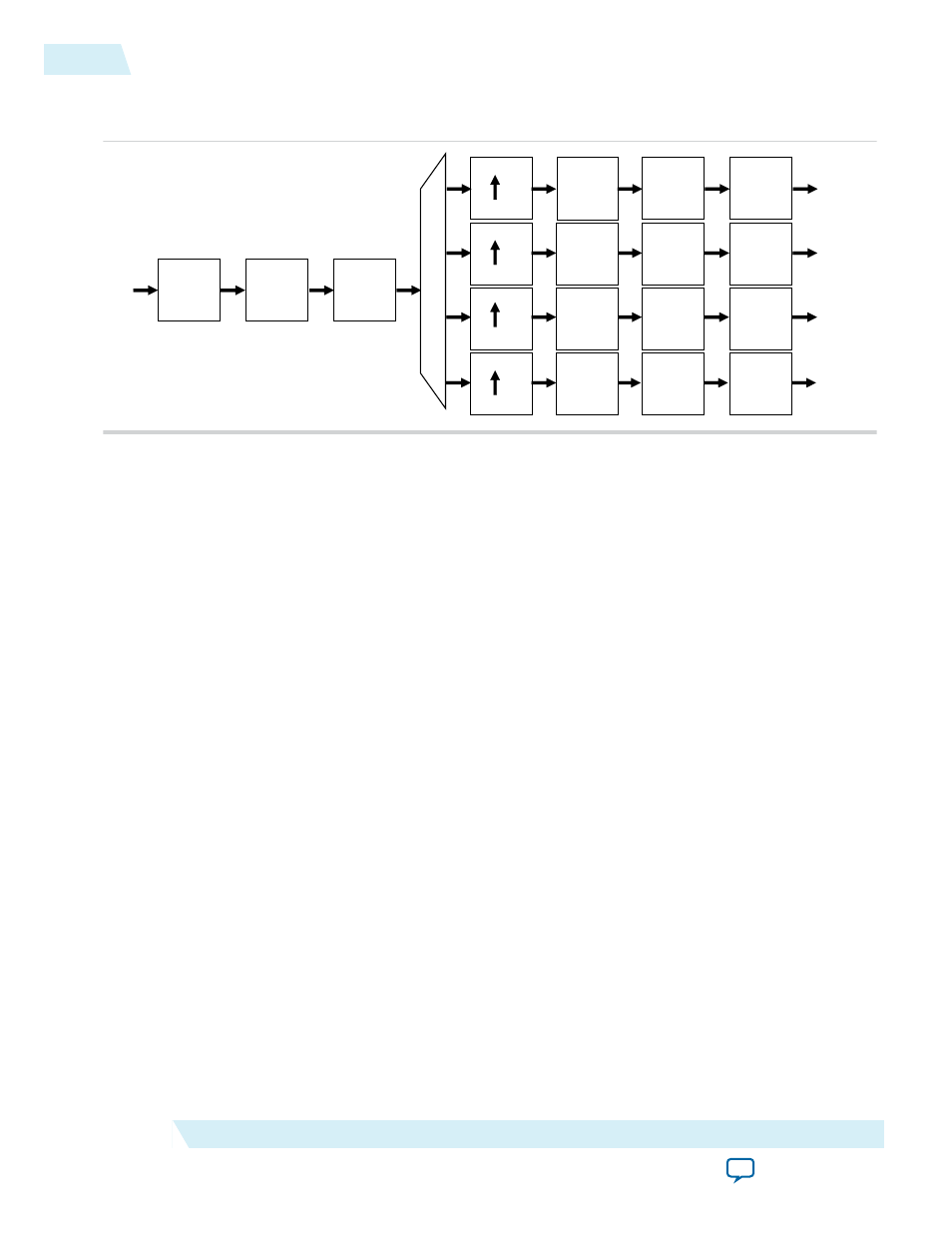
Figure 3-4: Single Input Multiple Output Architecture with Eight Channels
The symbols A, B, C, D, E, F, G, H are demultiplexed into four outputs A, E; B, F; C, G; and D, H
I
I
I
I
I
I
I
I
I
I
I
I
(A,B,C,D,E,F,G,H)
(A,E)
(B,F)
(C,G)
(D,H)
D
D
D
I
I
I
I
I
I
I
I
I
I
I
I
8
8
8
8
The required sampling frequency of the output data only allows time multiplexes of two channels per bus.
Therefore, you must configure the CIC filter with four output interfaces. The rate change factor must also
be at least four to exploit this architecture, but this example shows a rate change of eight.
Note: The CIC applies a SIMO when you select an interpolation filter and the number of interfaces is
greater than one.
The total number of input channels must be a multiple of the number of interfaces. To satisfy this require‐
ment, you may need to either insert dummy channels or use more than one CIC IP core.
The CIC transfers data as packets using Avalon Avalon-ST interfaces.
Related Information
An example design using multichannel MISO and SIMO architectures.
Output Options
You can select output options for the output data bit width and rounding options.
Output Data Width
If you select an output data width that is smaller than the full output resolution data width, apply the
Hogenauer pruning technique to reduce the data widths across the filter stages and hence the overall
resource utilization.
For a decimation filter, the gain at the output of the filter is:
G = RM
N
Therefore, the data width at the output stage for if full resolution is:
B
out
= B
in
+ Nlog
2
(RM)
where Bin is the input data width.
3-4
Output Options
UG-CIC
2014.12.15
Altera Corporation
CIC IP Core Functional Description