6 commissioning, 1 wiring, 1 general wiring guidelines – Pilz PNOZ m ES RS232 User Manual
Page 13: 2 interface configuration, 2 preparing for operation, Section 6, Commissioning, Wiring, General wiring guidelines, Interface configuration
Commissioning
Operating Manual PNOZ m ES RS232
1002701EN02
13
6
Commissioning
6.1
Wiring
6.1.1
General wiring guidelines
The wiring is defined in the circuit diagram of the PNOZmulti Configurator.
Please note:
}
Information given in the "Technical details" must be followed.
}
Use copper wire that can withstand 75°C.
6.1.2
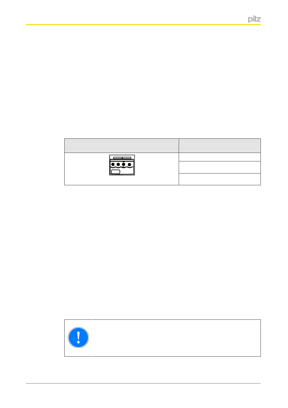
Interface configuration
Serial interface
RS232
Standard
TxD RxD GND
TxD (Transmit)
RxD (Receive)
GND (Ground)
6.2
Preparing for operation
The serial interface RS 232 is activated and detected depending on the USB interface on
the base unit:
}
USB interface on the base unit not connected
In this case, the serial interface RS 232 will be detected and activated by the base unit
as soon as the communication module has been connected to the base unit.
}
USB interface on the base unit connected
If the USB interface on the base unit is already connected, the "External" interface will
first need to be selected on the base unit display to enable the serial interface RS 232
on the base unit to be detected and activated (see operating manual for the base unit
for details of the setting).
6.2.1
Download modified project to the PNOZmulti safety system
As soon as an additional expansion module has been connected to the system, the project
must be amended using the PNOZmulti Configurator. Proceed as described in the operat
ing instructions for the base unit.
NOTICE
For the commissioning and after every program change, you must check
whether the safety devices are functioning correctly.