Pilz PNOZ mc4p DeviceNet coated version User Manual
Page 3
- 3 -
PNOZ mc4p (coated version) montie-
ren
Beachten Sie bei der Montage:
Achtung! Durch elektrostatische
Entladung können Bauteile der
Sicherheitssteuerung beschädigt
werden. Sorgen Sie für Entladung,
bevor Sie die Sicherheitssteuerung
berühren, z. B. durch Berühren einer
geerdeten, leitfähigen Fläche oder
durch Tragen eines geerdeten
Armbands.
• Montieren Sie das Sicherheitssystem in
einen Schaltschrank mit einer Schutzart
von mindestens IP54.
• Montieren Sie das Sicherheitssystem auf
eine waagrechte Tragschiene. Die
Lüftungsschlitze müssen nach oben und
unten zeigen (siehe Betriebsanleitung des
Basisgeräts PNOZ m0p, PNOZ m1p,
PNOZ m2p). Andere Einbaulagen können
zur Zerstörung des Sicherheitssystems
führen.
• Befestigen Sie das Sicherheitssystem mit
Hilfe der Rastelemente auf der Rückseite
auf einer Normschiene. Führen Sie das
Sicherheitssystem gerade auf die Norm-
schiene, so dass die Erdungsfedern am
Sicherheitssystem auf die Normschiene
gedrückt werden.
• Um die EMV-Anforderungen einzuhalten,
muss die Normschiene mit dem Schalt-
schrankgehäuse niederohmig verbunden
sein.
Basisgerät und Erweiterungsmodule
verbinden
Die Module werden mit Steckbrücken
verbunden. Es dürfen max. 8 Erweiterungs-
module und ein Feldbusmodul an ein
Basisgerät angeschlossen werden.
Auf der Geräterückseite des Basisgeräts
PNOZ m1p befinden sich 2 Stiftleisten.
• Stellen Sie sicher, dass kein Abschluss-
stecker gesteckt ist.
• Verbinden Sie das Basisgerät, die
Erweiterungsmodule und das Feldbus-
modul mit den mitgelieferten Steck-
brücken.
• Stecken Sie den Abschlussstecker auf das
letzte Erweiterungsmodul.
• Zwischen dem PNOZ mc4p (coated
version) und externen Wärmequellen muss
mind. 20 mm Abstand eingehalten werden.
Installing the PNOZ mc4p (coated
version)
Please note for installation:
Caution! Electrostatic discharge can
damage components on the safety
system. Ensure discharge before
touching the safety system, e.g. by
touching an earthed, conductive
surface or by wearing an earthed
armband.
• The safety system should be installed in a
control cabinet with a protection type of at
least IP54.
• Fit the safety system to a horizontal DIN
rail. The venting slots must point up and
down (see operating instructions for the
PNOZ m0p, PNOZ m1p and PNOZ m2p
base units). Other mounting positions
could damage the safety system.
• Use the notches on the rear of the safety
system to attach it to a DIN rail. Connect
the safety system to the DIN rail in an
upright position so that the earthing
springs on the safety system are pressed
on to the DIN rail.
• To comply with EMC requirements, the
DIN rail must have a low impedance
connection to the control cabinet housing.
Connecting the base unit and expansion
modules
The modules are linked via jumpers. A max.
of 8 expansion modules and one fieldbus
module may be connected to a base module.
There are 2 pin connectors on the rear of the
PNOZ m1p base module.
• Ensure that no terminator is connected.
• Connect the base module, the expansion
modules and the fieldbus module using the
jumpers supplied.
• The terminator must be fitted to the last
expansion module.
• A minimum distance of 20 mm must be
maintained between the PNOZ mc4p
(coated version) and external heat
sources.
Installer PNOZ mc4p (coated version)
Pour le montage, respectez les consignes
suivantes :
Attention ! Une décharge électrosta-
tique peut endommager les éléments
de l’automate de sécurité. Veillez à
vous décharger avant de toucher
l’automate de sécurité, par ex. en
touchant une surface conductrice
mise à la terre ou en portant un
bracelet de mise à la terre.
• Montez le système de sécurité dans une
armoire d’indice de protection IP 54 au
moins.
• Montez le système de sécurité sur un
profilé support horizontal. Les ouïes de
ventilation doivent être orientées vers le
haut et vers le bas (voir le manuel d’utili-
sation de l’appareil de base PNOZ m0p,
PNOZ m1p, PNOZ m2p). D’autres
positions de montage peuvent entraîner la
destruction du système de sécurité.
• Montez le système de sécurité sur un rail
DIN à l’aide du système de fixation situé
au dos de l’appareil. Installez le système
de sécurité droit sur le rail DIN de sorte
que les ressorts de mise à la terre sur le
système de sécurité reposent sur le rail
DIN.
• Pour respecter les exigences CEM, le rail
DIN doit être relié par une liaison à basse
impédance au corps de l’armoire.
Relier l’appareil de base et les modules
d’extension
Les modules sont reliés par des cavaliers de
pontage. Huit modules d’extension et un
module bus de terrain au maximum peuvent
être reliés à un appareil de base.
La face arrière de l’appareil de base
PNOZ m1p comporte 2 broches.
• Assurez-vous qu’aucune fiche de terminai-
son n’est branchée.
• Reliez l’appareil de base, les modules
d’extension et le module bus de terrain
avec les cavaliers de pontage livrés avec
les appareils.
• Branchez la fiche de terminaison sur le
dernier module d’extension.
• Une distance d’au moins 20 mm doit être
respectée entre le PNOZ mc4p (coated
version) et les sources de chaleur
externes.
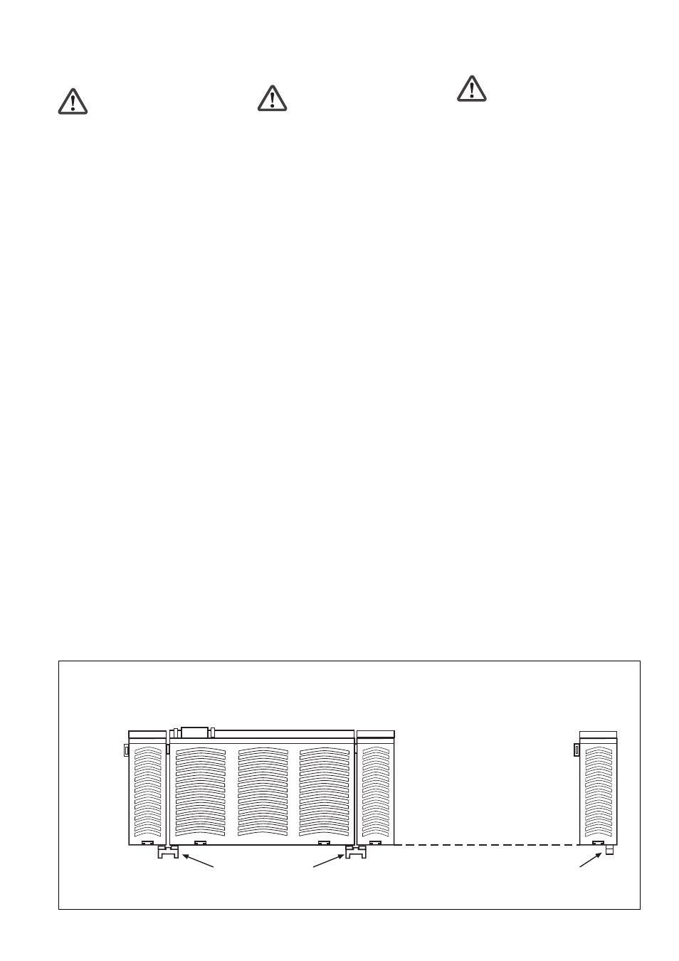
PNOZ mc4p links vom Basisgerät
montieren!
Install the PNOZ mc4p to the left of the
base unit!
Monter le PNOZ mc4p à gauche de
l’appareil de base !
Erweiterungsmodul 1
Expander module 1
Module d'extension 1
Erweiterungsmodul 8
Expander module 8
Module d'extension 8
Steckbrücke
Link
Cavalier de pontage
Abschlussstecker
Terminator
Fiche de terminaison
Feldbusmodul
Fieldbus module
Module bus de terrain
Basisgerät
Base unit
Appareil de base
PNOZ mc4p montieren
Installing the PNOZ mc4p
Installer PNOZ mc4p