6commissioning, 2 preparing for operation – Pilz PNOZ ms3p standstill / speed monitor User Manual
Page 23
Pilz GmbH & Co. KG, Felix-Wankel-Straße 2, 73760 Ostfildern, Germany
Telephone: +49 711 3409-0, Telefax: +49 711 3409-133, E-Mail: [email protected]
6-3
6.2
Preparing for operation
6
Commissioning
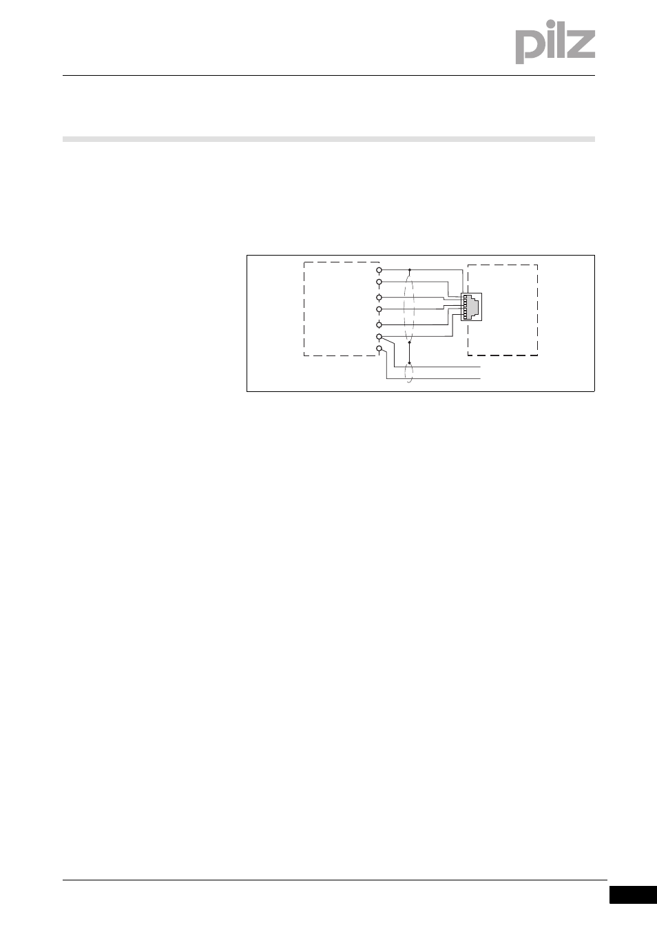
Encoder types: 24 V-HTL
`
Apply 24 VDC supply voltage to incremental encoder only
`
Do not terminate incremental encoder with Z0 = 120 Ohm
Fig. 6-2:
Connection to incremental encoder type 24 V-HTL
6.2.1.2
Connect the incremental encoder to the speed monitor via an adapter
Connect the incremental encoder to the speed monitor via an adapter
6-
Drehzahlwaechter_Betriebsb_Inkremen_ueber_Adapt_mit_24 V HTL_nur Inkremen an 5 V_BA
`
The adapter (e.g. PNOZ msi6p) is connected between the incremental
encoder and the drive. The output on the adapter is connected to the
RJ-45 female connector on the speed monitor.
`
The adapter can also be used without connecting to a drive. The sig-
nal lines can then be terminated directly at the adapter with Z
O
= 120
Ohm.
`
If the signal lines in the drive are already terminated with Z
O
=
120 Ohm, the incremental encoder may no longer be terminated.
`
The signals relevant for the speed monitor are utilised in parallel by
the adapter. The information stated in section 6.2.2.1 and in the
adapter operating manual must be observed when connecting the
supply voltage.
`
Supply 5 VDC to incremental encoder only. 24 V-HTL signals may not
be terminated.
X12
X22
Speed monitor
24 V DC
0 V
2
4
5
7
8
A
/A
B
/B
24 V
0 V
Incremental
encoder