Function description, Funktionsbeschreibung, Description du fonctionnement – Pilz PNOZ XV2 30/24VDC 2n/o 2n/o t User Manual
Page 2
- 2 -
• The correct opening and closing of the
Safety Gate limit switches and the safety
function output relays is tested
automatically in each on-off cycle
Function Description
The relay PNOZ XV2 provides a safety-
oriented interruption of a safety circuit. When
the operating voltage is supplied the LED
"Power" is illuminated. The unit is ready for
operation, when the reset circuit S13-S14 is
closed or a reset contact at S33-S34 was
opened and closed again. The status
indicator "start" illuminate.
• Input Circuit closed (e.g. the Emergency
Stop button is not pressed):
Relays K1, K2, K3 and K4 energise and
retain themselves. The status indicators
for "CH.1", "CH.2" and "CH.1(t)", CH.2(t)"
illuminate. The safety contacts (13-14/23-
24/37-38/47-48) are closed.
• Input Circuit is opened (e.g. Emergency
Stop is pressed)
Relays K1 and K2 de-energise. The status
indicators for "CH.1" and "CH.2" go out.
The safety contacts 13-14/23-24 will be
opened (redundant). Following the delay-
on de-energisation period, relays K3 and
K4 de-energise. The safety contacts 37-38
and 47-48 opens and the LED "CH.1(t)"
and "CH.2(t)" extinguish.
The unit may only be reset once the delay-
on-de-energisation period has lapsed and all
E-Stop and safety contacts are closed.
Interruption of Delay-on De-energisation:
By opening the contact Y39-Y40 i.e. pressing
a button connected the set delay-on de-
energisation will be interrupted and the safety
contacts 37-38 and 47-48 will open
immediately.
• Bei jedem Ein-Aus-Zyklus Überprüfung, ob
die Ausgangsrelais des Sicherheitsgerätes
richtig öffnen und schließen
Funktionsbeschreibung
Das Schaltgerät PNOZ XV2 dient dem sicher-
heitsgerichteten Unterbrechen eines Sicher-
heitsstromkreises. Nach Anlegen der
Versorgungsspannung leuchtet die LED
"Power". Das Gerät ist betriebsbereit, wenn
der Startkreis S13-S14 geschlossen ist oder
ein Startkontakt an S33-S34 geöffnet und
wieder geschlossen wurde. Die Statusanzeige
"start" leuchtet.
• Eingangskreis geschlossen (z. B. Not-Halt-
Taster nicht betätigt):
Relais K1, K2, K3 und K4 gehen in
Wirkstellung und halten sich selbst. Die
Statusanzeigen für "CH.1", "CH.2" und
"CH.1(t), "CH.2(t)" leuchten. Die Sicher-
heitskontakte 13-14/23-24/37-38/47-48 sind
geschlossen.
• Eingangskreis wird geöffnet (z. B. Not-Halt-
Taster betätigt):
Relais K1 und K2 fallen in die Ruhestellung
zurück. Die Statusanzeige für "CH.1" und
"CH.2" erlischt. Die Sicherheitskontakte 13-
14 und 23-24 werden redundant geöffnet.
Nach Ablauf der eingestellten
Verzögerungszeit fallen die Relais K3 und
K4 zurück. Die Sicherheitskonstakte 37-38
und 47-48 öffnen und die LED "CH.1(t)" und
"CH.2(t)" erlöschen.
Bevor das Gerät erneut gestartet werden
kann, muss die Verzögerungszeit abgelaufen
und alle Not-Halt- und Sicherheitskontakte
müssen wieder geschlossen sein.
Verzögerungszeit unterbrechen:
Durch Betätigen eines Reset-Tasters (Y39-
Y40) wird die eingestellte Verzögerungszeit
unterbrochen und die Sicherheitskontakte 37-
38 und 47-48 sofort geöffnet.
• Vérification à chaque mise en route du bon
fonctionnement des relais internes
Description du fonctionnement
Le relais PNOZ XV2 assure de façon sure,
l’ouverture d’un circuit de sécurité. A la mise
sous tension du relais (A1-A2), la LED
"Power" s'allume. Le relais est activé si le
circuit de réarmement S13-S14 est fermé ou
si le contact de réarmement sur S33-S34 a
été ouvert puis refermé. La LED "start"
s'allume.
• Circuits d'entrée fermés (poussoir AU non
actionné) :
Les relais K1, K2, K3 et K4 passent en
position travail et s'auto-maintiennent. Les
LEDs "CH.1", " CH.2" et "CH.1(t)",
"CH.2(t)" s'allument. Les contacts de
sécurité (13-14/23-24/37-38/47-48) sont
fermés.
• Circuits d'entrée ouverts (poussoir AU
actionné) :
Les relais K1 et K2 retombent. Les LEDs
"CH.1" et "CH.2" s'éteingnent. Les
contacts de sécurité 13-14/23-24
s'ouvrent. Au bout de la temporisation
affichée, les relais K3 et K4 retombent. Les
contacts de sécurité 37-38/47-48 s'ouvrent
et les LEDs "CH.1(t)" et "CH.2(t)"
s'éteignent.
Les canaux d'entrée doivent être refermés et
la temporisation écoulée avant de pouvoir
réarmer à nouveau le relais.
Arrêt de la temporisation
Un action sur un BP rellé au bornes Y39-Y40
(contact à ouverture) permet d'interrompre
prématurément la temporisation et d'ouvrir
instantanément les contacts de sortie 37-38
et 47-48.
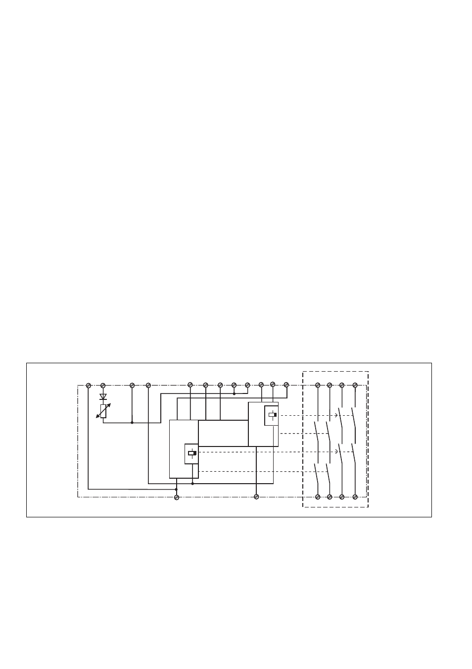
Fig. 1: Innenschaltbild/Internal Wiring Diagram/Schéma de principe
A1
A2
S13
S14
S12
S21
S34
47
48
S11
S22
S32
S31
13
37
14
38
K1
K2
23
24
CH1
CH2
Start
Unit
S33
+
-
Y39
Y40
K4
K3
*
* Isolation zum nicht markierten Bereich und der
Relaiskontakte zueinander: Basisisolierung
(Überspannungskategorie III), sichere Trennung
(Überspannungskategorie II)
Betriebsarten:
• Einkanaliger Betrieb:
Eingangsbeschaltung nach VDE 0113 und
EN 60204, keine Redundanz im Eingangs-
kreis, Erdschlüsse im Tasterkreis werden
erkannt.
• Zweikanaliger Betrieb: Redundanter Ein-
gangskreis, Erdschlüsse im Tasterkreis
und Querschlüsse zwischen den Taster-
kontakten werden erkannt.
* Insulation between the non-marked area
and the relay contacts: Basic insulation
(overvoltage category III), safe separation
(overvoltage category II)
Operating Modes
• Single-channel operation: Input wiring
according to VDE 0113 and EN 60204, no
redundancy in the input circuit, earth faults
are detected in the emergency stop circuit.
• Two-channel operation: Redundancy in the
input circuit, earth faults in the Emergency
Stop circuit and shorts across the
emergency stop push button are also
detected.
* Isolation de la partie non sélectionnée par
rapport aux contacts relais : isolation basique
(catégorie de surtensions III), isolation
galvanique (catégorie de surtensions II)
Modes de fonctionnement
• Commande par 1 canal : conforme aux
prescriptions de la EN 60204, pas de
redondance dans le circuit d’entrée, la
mise à la terre du circuit d’entrée est
détectée
• Commande par 2 canaux: circuit d’entrée
redondant, la mise à la terre et les courts-
circuits entre les contacts sont détectés.
- PNOZ XV2 3/24VDC 2n/o 2n/o t PNOZ XV2 0.5/24VDC 2n/o 2n/o fix PNOZ XV2 3/24VDC 2n/o 2n/o fix PNOZ XV2 10/24VDC 2n/o 2n/o fix PNOZ XV2 300/24VDC 2n/o 2n/o t PNOZ XV2.1P 30/24-240VACDC 2n/o 2n/o t PNOZ XV2.1P 3/24-240VACDC 2n/o 2n/o t PNOZ XV2.1P 0.5/24-240VACDC 2n/o 2n/o fi PNOZ XV2.1P 300/24-240VACDC 2n/o 2n/o t PNOZ XV2.1P C 30/24-240VACDC 2n/o 2n/o t PNOZ XV2.1P C 3/24-240VACDC 2n/o 2n/o t PNOZ XV2.1P C 300/24-240VACDC 2n/o 2n/o