Blower performance data cont, Versatec ultra series installation manual, Variable speed ecm motor – WaterFurnace Versatec Ultra User Manual
Page 26
26
VERSATEC ULTRA SERIES INSTALLATION MANUAL
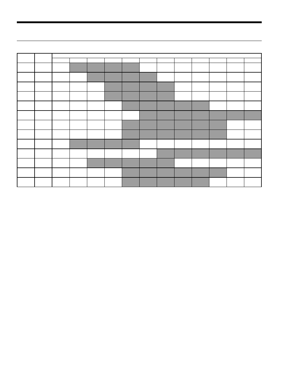
Blower Performance Data cont.
Variable Speed ECM Motor
Model
Max
esp
Airfl ow DIP Switch Settings
1
2
3
4
5
6
7
8
9
10
11
12
015
0.50
300
400
500
600
700
L
M
H
018
0.50
300
400
500
600
700
800
L
M
H
023
0.50
400
500
600
700
800
900
1000
1100
1200
L
M
H
024
0.50
400
500
600
700
800
900
1000
1100
1200
L
M
H
030
0.50
400
500
600
700
800
900
1000
1100
1200
L
M
H
036
0.50
600
700
800
900
1000
1100
1150
1225
1300
L
M
H
041
0.50
650
750
850
950
1050
1150
1250
1325
1375
1475
1550
1600
L
M
H
042
0.50
650
750
850
950
1050
1150
1250
1325
1375
1475
1550
1600
L
M
H
042
w/1hp*
0.75
800
1000
1100
1300
1500
1600
1800
L
M
H
048
0.50
650
750
850
950
1050
1150
1250
1325
1375
1475
1550
1600
L
M
H
048
w/1hp*
0.75
800
1000
1100
1300
1500
1600
1800
L
M
H
060
0.75
750
900
1000
1200
1400
1600
1700
1850
2000
2200
2300
2400
L
M
H
070
0.75
800
950
1100
1300
1500
1750
1950
2100
2300
L
M
H
11/10/09
Factory settings are at recommended L-M-H DIP switch locations.
Shaded regions are recommended for best performance. It is acceptable to operate outside of this area as long as the WSHP operates within the
guidlines of the Operating Limits table and Correction Factor tables.
Lowest and Highest DIP switch settings are assumed to be L and H respectively.
CFM is controlled within ±5% up to the maximum esp.
Max esp includes allowance for wet coil and standard fi lter