Fig. 3g-b – Vortech 2005-2009 Ford 4.6L 3V Mustang GT User Manual
Page 36
P/N: 8N020-120
© 2008 Vortech Engineering, LLC
All Rights Reserved, Intl. Copr. Secured.
23SEPT08v3.0(8N..120v3.0)MaxflowPwrClr
26
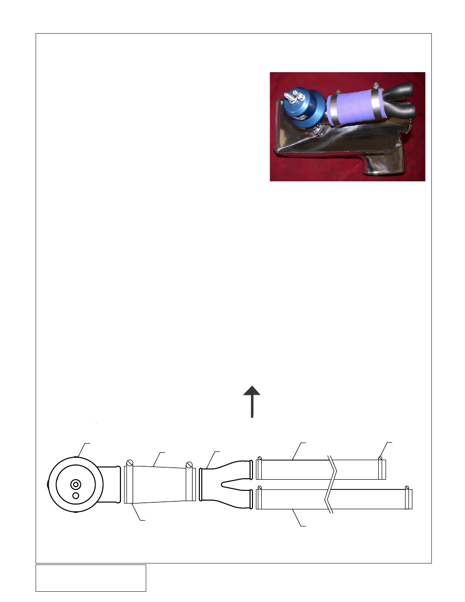
3G. COMPRESSOR BYPASS VALVE ASSEMBLY INSTALLATION (V-POWER/BULLITT KITS
ONLY)
1.
Attach the Maxflow Race Bypass Valve to the
flange located on the lower duct of the CAC
using the supplied hardware and gasket.
2.
Attach one end of the Ø 1.75" silicone coupler to
the outlet of the bypass valve and secure with
#28 hose clamp. (See Fig 3G-a)
3.
Insert the Ø 1.75" side of the bypass "Y" into the
open end of the Ø 1.75" silicone coupler and
secure with #28 hose clamp.
4.
Secure the two lengths of 1" hose cut to 16" and
17.5" to the two outlets on the bypass "Y" with
#16 hose clamps (See Figure 3G-b for orienta-
tion).
5.
Leave the opposite ends of the 1" hose open for
future attachment to the air inlet box.
6.
Attach a length of 5/32" vacuum hose to the
bypass valve and route to the vacuum port of the
fuel rail sensor.
7.
Cut a section of the factory hose and install the
vacuum TEE that is provided.
8.
Attach the vacuum hose from the bypass valve
to the TEE
#16 HOSE CLAMPS
(7R002-016)
BYPASS "Y"
Ø 1.75" X Ø 1.00"
(7P175-100)
RACE BYPASS VALVE
(8D204-001)
16" X Ø 1" HOSE
TRIM TO FIT
(7U034-016)
BLUE SLEEVE
Ø 1.75" X 4.00"
(7S175-400)
#28 HOSE CLAMPS
(7R002-028)
17.5" X Ø 1" HOSE
TRIM TO FIT
(7U034-016)
FRONT OF CAR
VIEWED FROM UNDERNEATH CAR
Fig. 3G-b
Fig. 3G-a (V-Power/Bullitt Kits Only)