Vortech 2005-2009 Ford 4.6L 3V Mustang GT User Manual
Page 34
P/N: 8N020-120
© 2008 Vortech Engineering, LLC
All Rights Reserved, Intl. Copr. Secured.
23SEPT08v3.0(8N..120v3.0)MaxflowPwrClr
24
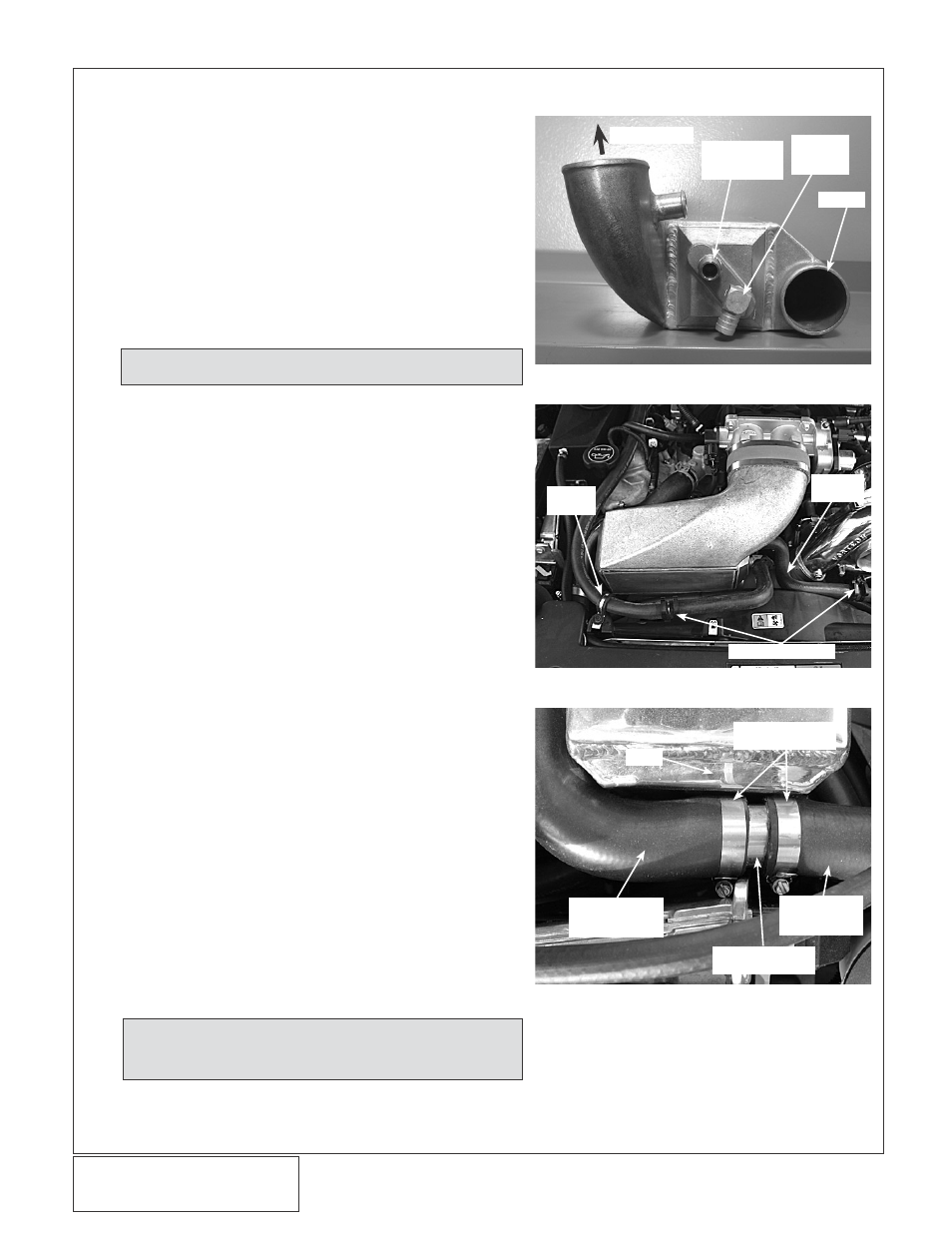
3F. COOLER CORE INSTALLATION
DISCHARGE
3/4"
STRAIGHT
FITTING
3/4" x 90°
FITTING
INLET
ADEL
CLAMP
“S”
HOSE
HOSE UNIONS
Fig. 3F-a
Fig. 3F-b
Fig. 3F-c | 2007-2009 Models Only
1.
Locate the charge air cooler assembly.
2.
Attach the 4.5" x 2" sleeve to the throttle body and
secure with a #72 hose clamp.
3.
Install the 1/2"NPT x 3/4" barb 90° and straight fit-
tings into the charge cooler as shown. (See Fig.
3F-a.)
4.
Attach the long end of the 2.75" (3.0" if installing
the V-Power upgrade) silicone elbow to the cooler
inlet and loosely install a #44 hose clamp. The
open end of the elbow should be facing up as it
will be attached to the supercharger discharge.
5.
Lower the cooler assembly into position. Attach the
open end of the previously installed 2.75" elbow to
the supercharger discharge and loosely install a
#44 hose clamp.
6.
Attach the cooler discharge to the previously
installed sleeve on the throttle body. Secure with a
#72 hose clamp.
7.
Tighten all cooler clamps at this time.
8.
Locate the remaining 3/4" molded 90° hose. Trim
approximately 5" from the long end and attach the
short end to the 3/4" x 90° fitting previously
installed in the cooler. Secure with the nylon ratch-
et clamp provided.
9.
Install a 3/4" hose union into the open end of the
previously installed hose. Attach a section of 3/4"
hose approximately 32" long to the union. Route
the open end of the hose to the surge tank. Using
the remaining adel clamp and factory hardware,
secure the hose to the factory coolant reservoir
mounting location. (See Figs. 3F-q, 3F-b for assis-
tance.) Secure all hose connections with the sup-
plied nylon ratchet clamps.
10. (Standard HO only) Locate the supplied “S”
shaped hose. Trim approximately 1" from the short
end and attach it to the straight fitting previously
installed in the cooler. Install a 3/4" hose union into
the open end of the “S” hose. Attach a section of
3/4" hose approximately 24" long to the union and
route to the driver’s side and down to the water
cooler. Trim for best fit and connect to the 3/4"
hose union previously installed in the 90° short
rubber hose attached to the top water port on the
CAC cooler.
#24 HOSE
CLAMPS
TO
THERMOSTAT
HOUSING
CONNECTED
TO
RADIATOR
Ø1.5 HOSE
UNION
CAC
NOTE: The installation of this hose section should
maintain an “uphill” routing without dips or
kinks.
NOTE: See section 3G for bypass valve installation.