Vortech 2005-2009 Ford 4.6L 3V Mustang GT User Manual
Page 21
P/N: 8N020-120
© 2008 Vortech Engineering, LLC
All Rights Reserved, Intl. Copr. Secured.
23SEPT08v3.0(8N..120v3.0)MaxflowPwrClr
11
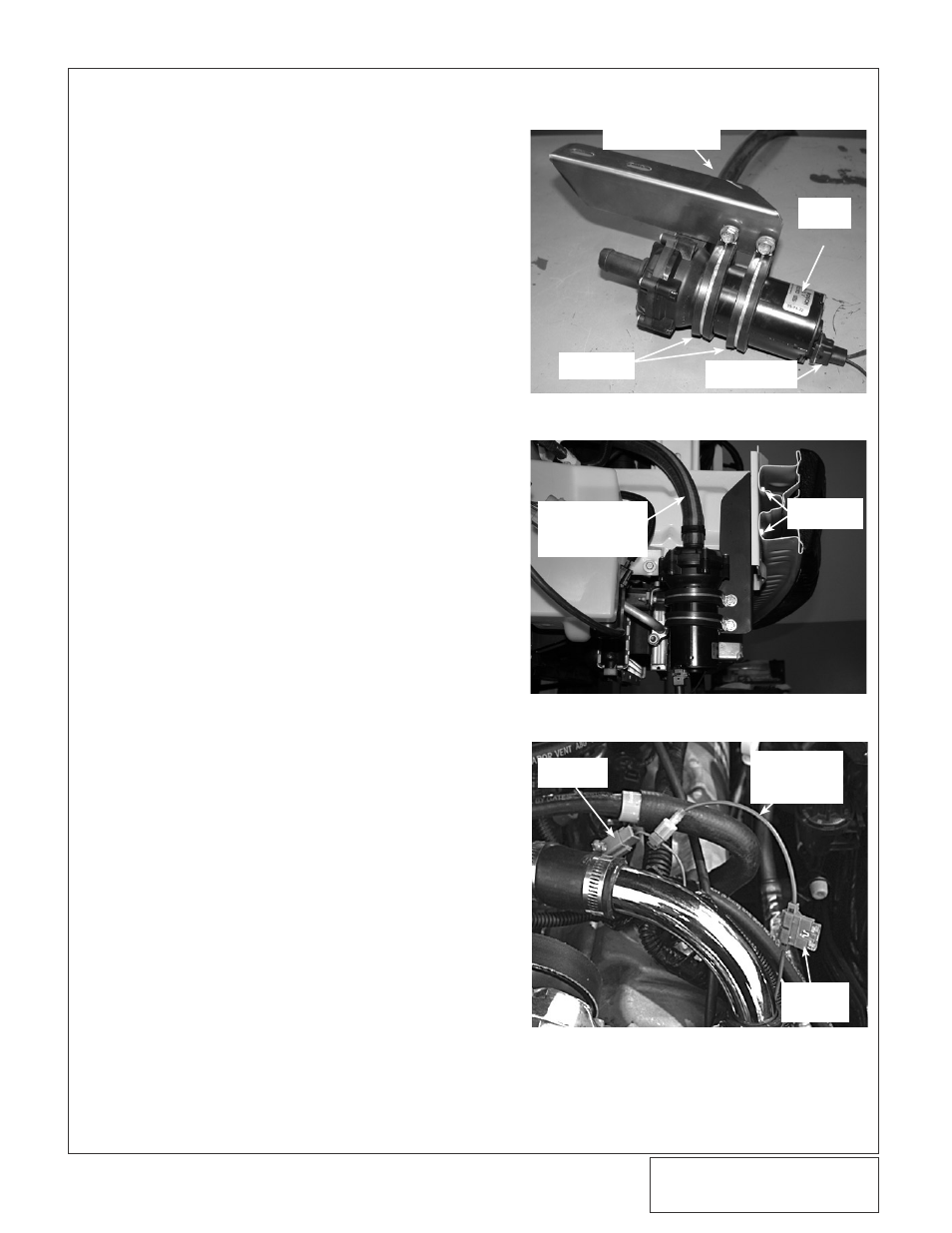
3B. WATER COOLER ASSEMBLY INSTALLATION, CONT’D
10. Locate assembly 8N104-125. Confirm that the
assembly is complete.
11. Attach the provided ring terminal to the ground
wire on the suplied water pump plug harness.
Connect the supplied length of 16GA wire to the
positive wire using the supplied butt connector.
Connect the water pump harness to the water
pump.
12. Locate the supplied water pump (8F001-403), two
2-3/8" adel clamps, and water pump mounting
bracket. Place the adel clamps on the water
pump. Using the supplied 1/4-20 hardware,
secure the water pump and clamps to the mount-
ing bracket. When installing, attach the water
pump ground wire to one of the water pump
mounting clamps using the previously installed
ring terminal. (See Fig. 3B-g.)
13. Attach the pump assembly to the two 8mm x
35mm long bolts previously installed and secure
using the 8mm nuts and washers provided. (See
Fig. 3B-h.)
14. Route the positive wire up towards the driver’s
side valve cover.
15. Locate the ballast resistor plug. Install the sup-
plied T-tap connector, cut the water pump positive
wire (from the water pump) for best fit, attach the
supplied male spayed connector and attach to the
wire T-tap connnector. (See Fig., 3B-i.)
16. Cut the water pump positive wire and install the
inline fuse holder and fuse. Install the wire loom
provided and secure away from heat and moving
parts. (See Fig. 3B-i.)
Fig. 3B-g
Fig. 3B-h
MOUNTING
BRACKET
ADEL
CLAMP
PLUG
HARNESS
WATER
PUMP
HOSE TO
PASSENGER’S
SIDE SHOCK
TOWER
8mm
HARDWARE
Fig. 3B-i
BALLAST
RESISTOR
POSITIVE
WIRE
TO WATER
PUMP
SUPPLIED
FUSE
HOLDER