Vortech 2009-2010 5.7L Hemi Cars (Charger, Challenger, 300C) User Manual
Page 26
P/N: 4CL020-015 v1.0, 12/02/2014
©2014 Vortech Engineering, Inc.
All Rights Reserved, Intl. Copr. Secured
12
8.
CHARGE AIR COOLER/DISCHARGE ASSEMBLY INSTALLATION, CONT’D
G.
(See “Discharge Tube Identification” below).
Locate discharge tube B & install the supplied
silicone sleeve onto the shorter leg of the tube
with the 45º bends. Place hose clamps hand tight
onto the sleeve but do not tighten all the way.
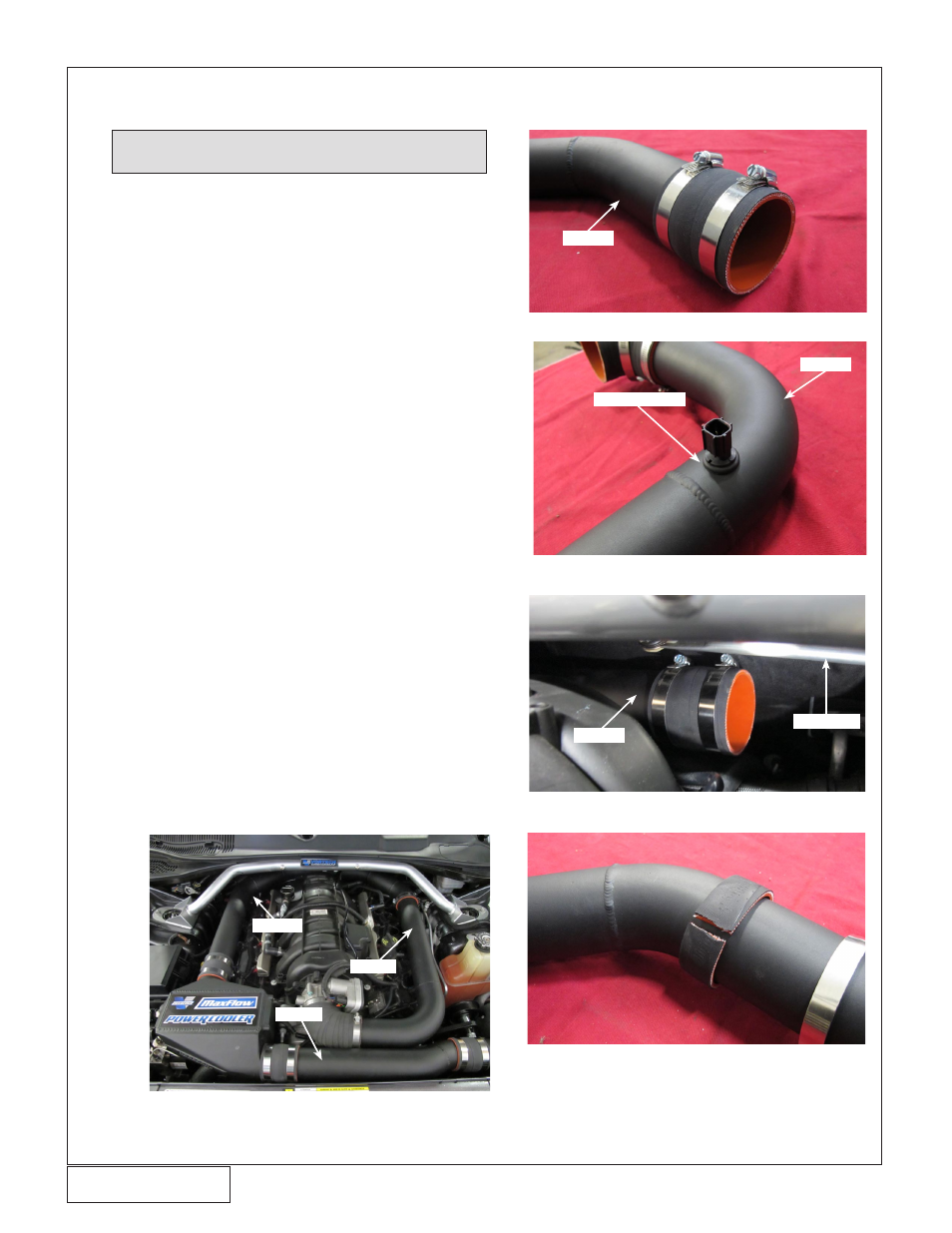
H. On the shorter leg of discharge tube B, orientate
the hose clamps so they are pushed slightly to-
wards the back. This is in preparation for a later
step. (See Fig. 8-e)
I. Slide a silicone coupler onto the long leg of
discharge tube B, then slide the tube onto the
charge air cooler. Make sure discharge tube B is
resting on the discharge tube support bracket on
the passenger side. This will leave the other end
of the tube near the back of the engine, close to
the firewall.
J. Locate discharge tube C & install the factory IAT
sensor, using the supplied rubber grommet. (See
Fig. 8-f)
K. Install 90 degree silicone elbow onto the throttle
body.
L. Grab discharge tube C & place the tube so that
the section with the two 45º bends are near the
back of the engine, close to the firewall. Slide
discharge tube C into the silicone coupler previ-
ously installed onto discharge tube B (See Fig.
8-g). Insert the other end of discharge tube C into
the 90º silicone elbow previously installed on the
throttle body.
M. Locate supplied 1” silicone coupler & cut it so it
can be placed over discharge tube C. Place the
cut coupler over discharge tube C & place it in a
way to trap the drivers side discharge tube support
bracket between the coupler & discharge tube C.
Place supplied hose clamp over the coupler. (See
Fig. 8-h)
NOTE: For the following procedures, it’s important to
NOT tighten the hose clamps until Step Q.
Fig. 8-e
Fig. 8-f
Fig. 8-g
Fig. 8-h
Discharge Tube Identification
Tube C
Tube B
Tube A
Tube B
Wiper Arm
Tube B
Tube C
IAT SENSOR