Hart status byte 3: extended device stat, Output instance (102), Unlatch alarm bits – Spectrum Controls 1734sc-OE2CIH User Manual
Page 51
Chapter 4: OE2CIH and HART
4-15
User’s Manual Pub. 0300272-01 Rev. A.0
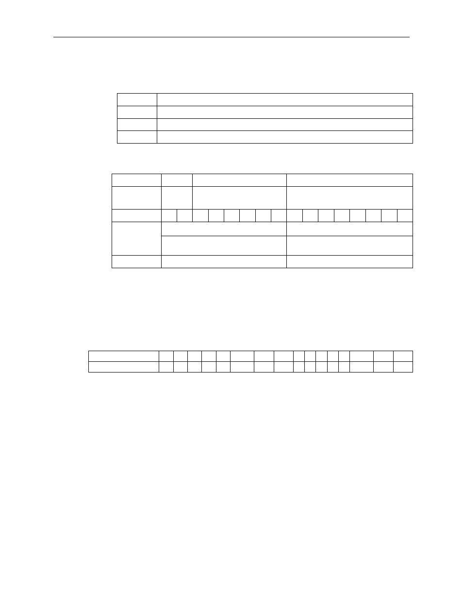
HART STATUS BYTE 3: Extended Device Status
This is the first byte returned with Command 9 by HART revision 6 and 7 devices. It is
not used and always zero (0) for HART revision 5 devices:
Bit Mask Definition
0×04 = Critical Power Failure
0×02 = Device Variable Alert
0×01 = Maintenance Required
Output Instance (102)
Table 4-10 Output Assembly
Instance:
ID:
Description:
Total Size:
Output
102
Output words
6 bytes
Bit
15 14 13 12 11 10 09 08 07 06 05 04 03 02 01 00
Output
6 bytes
0×00 to 0×05
High Byte–Channel 0 Output
Low Byte–Channel 0 Output
High Byte–Channel 1 Output
Low Byte–Channel 1 Output
High Byte–Channel 1 Unlatch Alarms Low Byte–Channel 0 Unlatch Alarms
Unlatch Alarm Bits
The unlatching is performed when the unlatch bit is set (1) and the alarm condition no
longer exists. If the alarm condition persists then the unlatch bit has no effect. It is up to
you to keep the unlatch bit set until you get verification from the appropriate channel
status word that the alarm status bit has cleared (0). It is then up to you to reset (0) the
unlatch bit. The module will not latch an alarm condition if a transition from no alarm
condition to alarm condition occurs, and the unlatch bit is set (1).
Word/Bit
15
14
13
12
11
10
9
8
7
6
5
4
3
2
1
0
Channel Alarm Unlatch
0
0
0
0
0
UOC1
UH1
UL1
0
0
0
0
0
UOC0
UH0
UL0
Bit 0:
UL0
Unlatch Low Clamp Alarm Channel 0
Bit 1:
UH0
Unlatch High Clamp Alarm Channel 0
Bit 2:
UOC0 Unlatch Open Circuit Alarm Channel 0
Bits 3~7: Reserved. Set to 0
Bit 8:
UL1
Unlatch Low Clamp Alarm Channel 1
Bit 9:
UH1
Unlatch High Clamp Alarm Channel 1
Bit 10: UOC1 Unlatch Open Circuit Alarm Channel 1
Bits 11~153~7: Reserved. Set to 0