Channel status bits, Module status, Channel hard fault – Spectrum Controls 1734sc-OE2CIH User Manual
Page 48
4-12
Chapter 4: OE2CIH and HART
User’s Manual Pub. 0300272-01 Rev. A.0
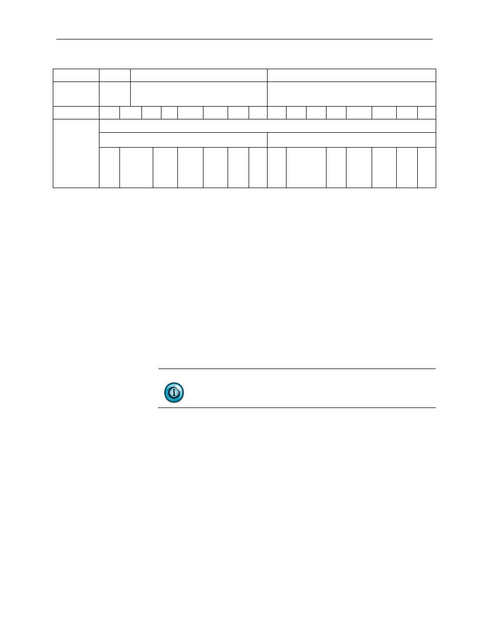
Table 4-8 Input-Only Assembly
Instance:
ID:
Description:
Total Size:
100
3
Channel Status Only
12 Bytes RSL 5 K (DeviceNet 8 bytes)
Bit
15
14
13 12
11
10
09
08 07
06
05
04
03
02
01
00
Analog
data 4
bytes
0Ч00-0Ч03
Module Status - UINT
High Byte–Channel 1 Status
Low Byte–Channel 0 Status
HF
Bits
13-14
not
used
OC
HCA LCA CM CF HF
Bits 05-
06 not
used
OC HCA LCA CM CF
Channel Status Bits
CF = Channel Fault status; 0 = no error; 1 = any fault (LCA, HCA, OC)
CM = Calibration Mode; 0 = no calibration taking place; 1 = calibration in
process
LCA = Low Clamp Alarm; 0 = no alarm; 1 = Low alarm equal to or less than
Low Limit user value.
HCA = High Clamp Alarm; 0 = no alarm; 1 = High alarm equal to or greater
than High Limit user value.
OC = Open Circuit; 0 = no error; 1 = open circuit
HF = Hard Fault; 0 = no fault; 1 = fault
Module Status
0 = Module OK
1 = Watchdog Fault
2 = Channel Hard Fault
3 = Bad or No Configuration
NOTE
The above status codes are in priority order where multiple conditions
may exist.
Channel Hard Fault
In the case where one of the HART modem CPUs cannot be communicated with, the
channel is placed in a Hard Fault Mode. The HF bit is set for that channel and the Module
Status is set to 2. The HART modem CPU is held in reset until the module is power-
cycled. This action may or may not disable the output since the reset line runs through the
same isolation IC as TX and RX. The channel status LED is set to solid Red while the
Module Status LED is set to flashing Red. The other channel is allowed to operate
normally.