1 wiring diagram, 1 wiring diagram -9 – Spectrum Controls 1734sc-OE2CIH User Manual
Page 23
Chapter 2: Installation and Wiring
2-9
User’s Manual Pub. 0300272-01 Rev. A.0
Noise Prevention
Route field wiring away from any other wiring and as far as possible from
sources of electrical noise, such as motors, transformers, contactors, and AC
devices. As a general rule allow at least 15.2 cm (6 in.) of separation for every
120 V of power.
Routing field wiring in a grounded conduit can reduce electrical noise.
If field wiring must cross AC or power cables, ensure that they cross at right
angles.
If noise persists for a device, try grounding the opposite end of the cable shield
or ground both ends of the shield.
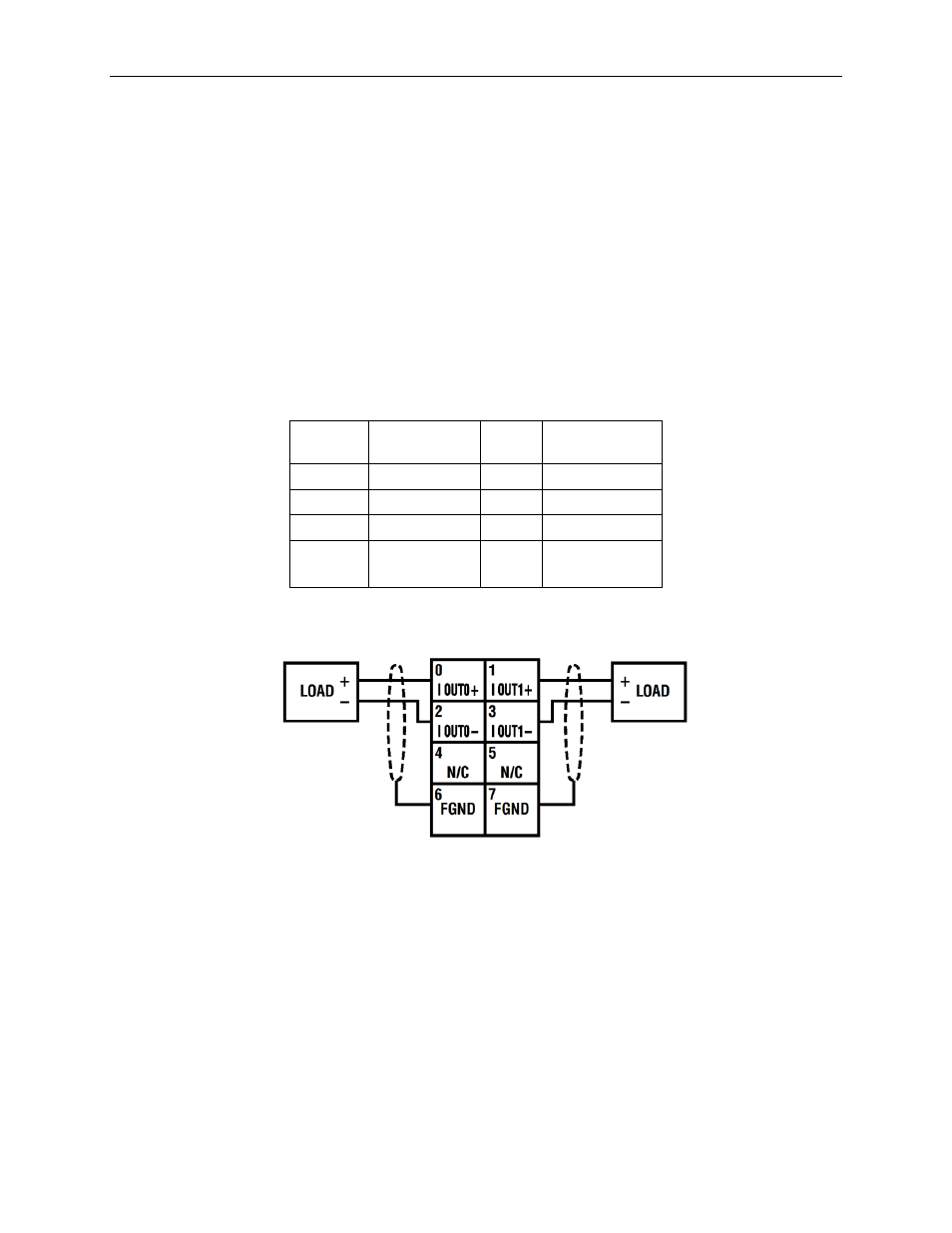
2.5.1 Wiring Diagram
Refer to the following wiring diagrams for field wiring connections.
Table 2-1 (2 Channel Terminal Block Pinout)
RTB
Pin#
Usage
RTB
Pin#
Usage
0
Isolated 0ut0+
1
Isolated 0ut1+
2
Isolated Out0-
3
Isolated Out1-
4
Unused
5
Unused
6
Chassis GND
(FGND)
7
Chassis GND
(FGND)
Figure 2-1 (OE2CIH Wiring Diagram)