Hart status bits, Hart status byte 1: communication status, Hart status byte 2: field device status – Spectrum Controls 1734sc-OE2CIH User Manual
Page 50
4-14
Chapter 4: OE2CIH and HART
User’s Manual Pub. 0300272-01 Rev. A.0
HART STATUS BITS:
INIT = HART device detected
FAIL = No device found or communication failed
MAFLT = HART does not match analog loop current
MSGRDY = Ladder pass-through message available
DDLDR = Device Data update Ladder
DDLGX = Device Data update Logix
SUA = Status Update Available, Cmd 48 data changed
FAULT= HART device reports a fault
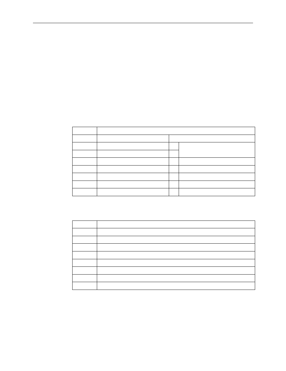
HART STATUS BYTE 1: Communication Status / Response Code
This if the first status byte returned in a Slave-to-Master frame. It is used for both
Communication Status and Response Code. If the Most Significant Bit is set a
communication error has been reported by the device. Otherwise the remaining 7 bits
contain the response code.
Bit Mask Definition
0×80 = 1= Communication Error
0 = Response Code
0×40 = Vertical Parity Error
Bits 6..0 = Enum 0 to 127, command-
dependent
0×20 = Overrun Error
0×10 = Framing Error
0×08 = Longitudinal Parity Error
0×04 = Reserved, always 0
0×02 = Buffer Overflow
0×01 = Reserved, always 0
HART STATUS BYTE 2: Field Device Status
This is the second status byte returned in a Slave-to-Master frame:
Bit Mask Definition
0×80 = Device Malfunction
0×40 = Configuration Changed
0×20 = Cold Start
0×10 = More Status Available
0×08 = Loop Current Fixed
0×04 = Loop Current Saturated
0×02 = Non-Primary Variable Out of Limits
0×01 = Primary Variable Out of Limits