Spectrum Controls 1769sc-IR6I User Manual
Page 68
D-4
Compact™ IO Isolated RTD/Resistance Module
User’s Manual Pub. 0300241-01 Rev. A
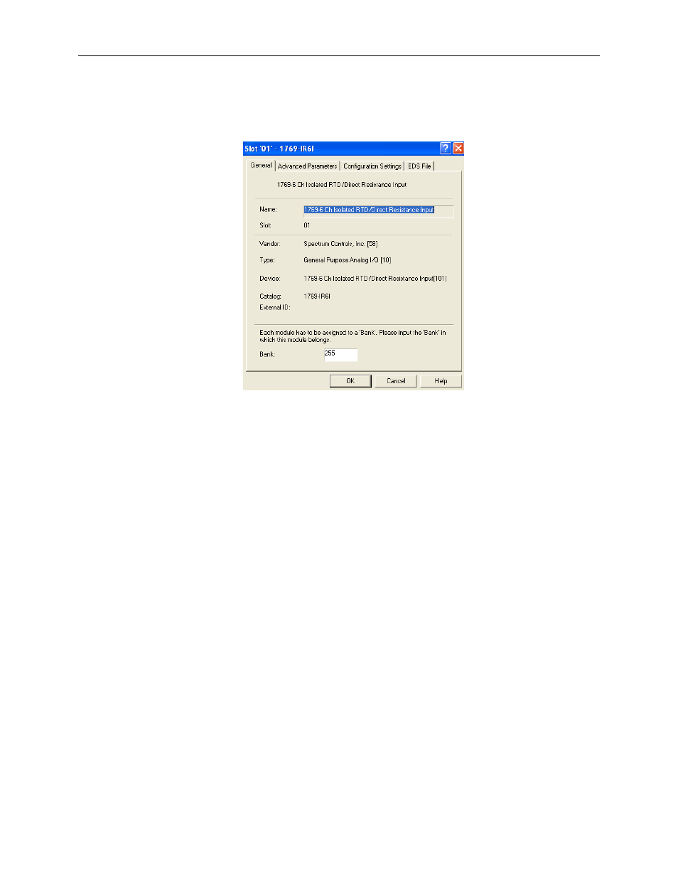
click on the first empty slot after the 1769-ADN. From the module list on the left, select
the 1769sc-IR6I. The module should appear in the empty slot. Double-click on the
1769sc-IR6I module in slot 1 and the following 1769sc-IR6I configuration screen
appears:
Enter 1 into the bank field at the bottom of the screen.
By default, the 1769sc-IR6I module contains eight input words and no output words.
Click on the “Advanced Parameters” tab. This screen allows you to change the input data
size. You can select from 1 word all the way up to the default, which is 8 words. Click
OK or CANCEL to exit this screen and return to the Configuration screen.
You may leave the Electronic Keying to “Compatible Module”. It is not recommended
to Disable Keying, but if you are not sure of the exact revision of your module, selecting
Compatible Module requires that a 1769sc-IR6I module be installed in slot 1.
Click on the “Configuration Settings” tab. Each of the 6 RTD/resistance input channels
are enabled by default. To disable a channel, double-click on the channel number and
change the enable state to disabled. Go ahead and finish the module configuration by
choosing your Data Format, Input Type, Temperature Units, Open-Circuit Condition and
Filter Frequency for each channel you intend to use. See Channel Configuration on page
4-2 for a complete description of each of these configuration categories.
In this example, channels 0 through 5 are being used. All 6 channels have 100Ω Pt 385
RTDs connected. A 10Hz Filter Frequency (the default) is used for all 6 channels, along
with receiving the RTD/resistance input data in Engineering Units. We also chose °F for
the Temperature Units. This selection, coupled with choosing Engineering Units for the
data format allows us to receive the data into the controller’s tag database as actual
temperature data in °F. The Open-Circuit Detection is Upscale. This means that if an
open-circuit condition should occur at any of the 6 RTD/resistance input channels, the
input value for that channel is the full-scale value selected by the input type and data
format. We can therefore monitor each channel for full scale (open-circuit) as well as
monitor the Open-Circuit bits in Input word 6, for each channel. When complete, the
configuration screen looks like the following: