8 cyclic lead compensation (bit 4), 6 compact™ io isolated rtd/resistance module – Spectrum Controls 1769sc-IR6I User Manual
Page 38
4-6
Compact™ IO Isolated RTD/Resistance Module
User’s Manual Pub. 0300241-01 Rev. A
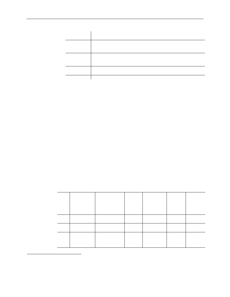
Table 4-4 (Open-Circuit Response)
Response
Option
Definition
Upscale
Sets the input data value to full upper scale value of channel data word.
The full-scale value is determined by the selected input type and data
format.
Downscale
Sets the input data value to full lower scale value of channel data word.
The low scale value is determined by the selected input type and data
format.
Last State
Sets the input data value to the last input value prior to the detection of
the open-circuit.
Zero
Sets the input data value to 0 to force the channel data word to 0.
4.2.8
Cyclic Lead Compensation (Bit 4)
For each channel, the module measures lead resistance in one of two ways. Set bit 4 to 0
to enable measurement and compensation of lead resistance every 6 module scans. One
channel is measured per module update to limit the impact to channel throughput. You
can also implement a lead wire calibration cycle any time, at your command, by enabling
and then disabling this bit in your control program.
6
Regardless of the state of bit 4, lead
wire compensation occurs automatically on a system mode change from Program-to-Run
or if any online configuration change is made to a channel.
4.2.9
Selecting Input Filter Frequency (Bits 0 through 2)
The input filter selection field allows you to select the filter frequency for each channel 0
through 5. The filter frequency affects the following, as explained later in this chapter:
•
Noise rejection characteristics for module inputs
•
Cut-Off Frequency
•
Repeatability
•
Module update time
The table below summarizes the effects of each filter selection.
Table 4-6 (Filter Effects)
Input
Filter
Channel
Update
Time
Lead
Compensation
Disabled
Channel
Update
Time
Lead
Compensation
Enabled
7
Cut-Off
Frequency Repeatability
NMRR
50 Hz
Rejection
NMRR
60 Hz
Rejection
4.17
Hz
242 msec
964 msec
1 Hz
See Appendix
A
74 dB
74 dB
10.0
Hz
102 msec
404 msec
2 Hz
See Appendix
A
70 dB
70 dB
16.7
Hz
62 msec
244 msec
4 Hz
2x(4.17 Hz
values)
From Appendix
A
65 dB
NA
6
Not all controllers allow online configuration changes. Refer to your controller’s user manual for details. During
an online configuration change, input data for that channel is not updated by the module.
7
If lead compensation is enabled, use this column for channel update times.