Spectrum Controls 1769sc-IR6I User Manual
Page 29
Chapter 3: Installation and Wiring
3-9
User’s Manual Pub. 0300241-01 Rev. A
•
Refer to Industrial Automation Wiring and Grounding Guidelines, Allen-
Bradley publication 1770-4.1, for additional information.
3.7.2
RTD Wiring Considerations
Since the operating principle of the RTD module is based on the measurement of
resistance, take special care when selecting your input cable. For 2-wire or 3-wire
configurations, select a cable that has a consistent impedance throughout its entire length.
The RTD module requires three wires to compensate for lead resistance
error. We recommend that you do not use 2-wire RTDs if long cable
runs are required, as it reduces the accuracy of the system. However, if
a two-wire configuration is required, reduce the effect of the lead wire
resistance by using a lower gauge wire for the cable (for example, use
AWG #16 instead of AWG #24). The module’s terminal block accepts
two AWG #14 gauge wires.
When using a 3-wire configuration, the module compensates for resistance error due to
lead wire length. For example, in a 3-wire configuration, the module reads the resistance
due to the length of one of the wires and assumes that the resistance of the other wire is
equal. If the resistances of the individual lead wires are much different, an error may
exist. The closer the resistance values are to each other, the greater the amount of error
that is eliminated.
To ensure temperature or resistance value accuracy, the resistance
difference of the cable lead wires must be equal to or less than 0.01Ω .
To insure that the lead values match as closely as possible:
•
Keep lead resistance as small as possible and less than 25Ω .
•
Use quality cable that has a small tolerance impedance rating.
•
Use a heavy-gauge lead wire which has less resistance per foot.
3.7.3
Terminal Door Label
A removable, write-on label is provided with the module. Remove the label from the
door, mark your unique identification of each terminal with permanent ink, and slide the
label back into the door. Your markings (ID tag) will be visible when the module door is
closed.
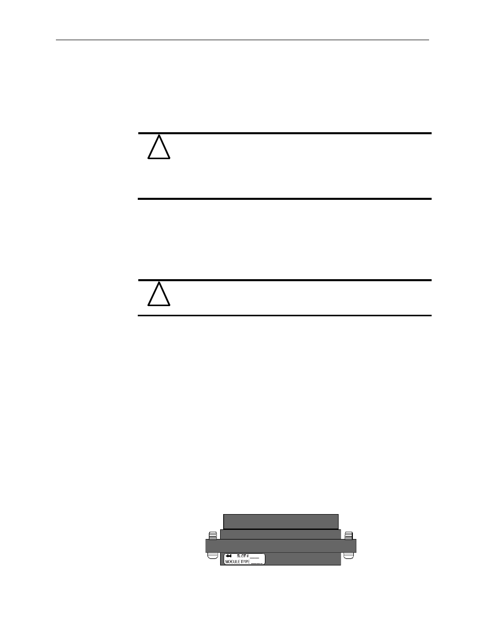
3.7.4
Removing and Replacing the Terminal Block
When wiring the module, you do not have to remove the terminal block. If you remove
the terminal block, use the write-on label located on the side of the terminal block to
identify the module location and type.
!
Attention
!
Attention