Spectrum Controls 1769sc-IR6I User Manual
Page 67
Appendix D: Configuring the IR6I to be Used with a 1769-AND DeviceNet Adapter
D-3
User’s Manual Pub. 0300241-01 Rev. A
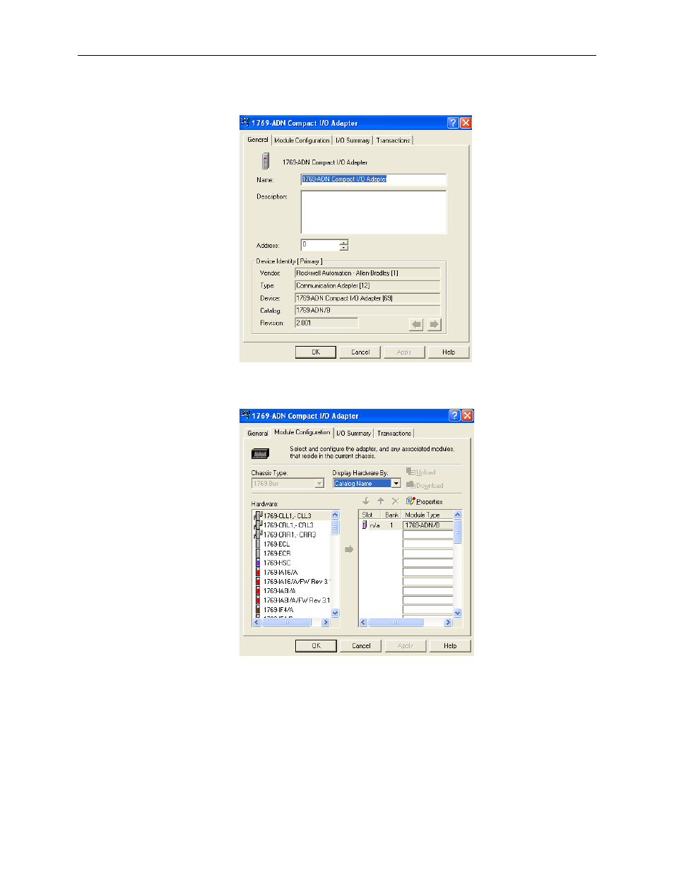
To configure I/O for the adapter, double-click on the adapter that you just placed on the
network, and the following screen appears:
At this point, you may modify the adapters DeviceNet node address, if desired. Next,
click on the Module Configuration tab. The following screen appears:
Section D.5
Configuring
the 1769sc-IR6I
The 1769-ADN appears in slot 0. Your I/O modules, power supplies, end cap and
interconnect cables must be entered in the proper order, following the 1769 I/O rules
contained in the 1769-ADN user’s manual. For simplicity sake, we placed the 1769sc-
IR6I in slot 1 to show how it is configured. As a minimum, a power supply and end cap
must also be placed after the 1769sc-IR6I module. To add the 1769sc-IR6I to bank 1,