Spectrum Controls 1769sc-IR6I User Manual
Page 11
Chapter 1: Module Overview
1-3
User’s Manual Pub. 0300241-01 Rev. A
1.1.4
Hardware Features
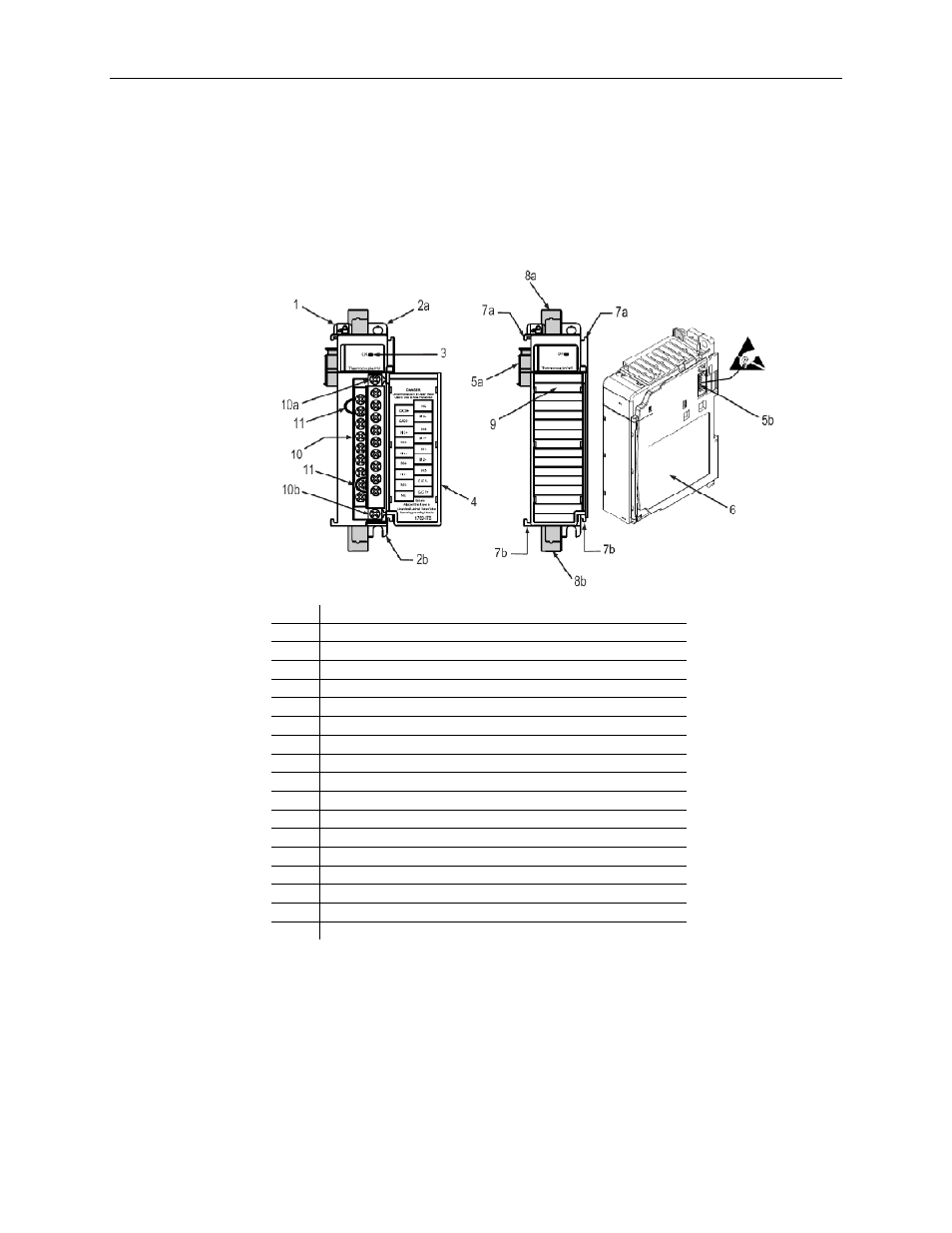
The Isolated RTD/resistance module contains a removable terminal block (spare part
number 1769-RTBN18) providing connections for six 3-wire inputs for any combination
of RTD and resistance input devices. Channels are wired as differential inputs. The
illustration below shows the hardware features of the module.
The illustration below shows the module’s hardware features.
Item Description
1 Bus
lever
2a
Upper panel mounting tab
2b
Lower panel mounting tab
3 Module
status
LED
4
Module door with terminal identification label
5a
Movable bus connector (bus interface) with female pins
5b
Stationary bus connector (bus interface) with male pins
6 Nameplate
label
7a
Upper tongue-and-groove slots
7b
Lower tongue-and-groove slots
8a
Upper DIN rail latch
8b
Lower DIN rail latch
9
Write-on label for user identification tags
10
Removable terminal block (RTB) with finger-safe cover
10a
RTB upper retaining screw
10b
RTB lower retaining screw
11 CJC
sensors
Module configuration is normally done via the controller’s programming software. In
addition, some controllers support configuration via the user program. In either case, the
module configuration is stored in the memory of the controller. Refer to your controller’s
user manual for more information.