Spectrum Controls 1769sc-IR6I User Manual
Page 30
3-10
Compact™ IO Isolated RTD/Resistance Module
User’s Manual Pub. 0300241-01 Rev. A
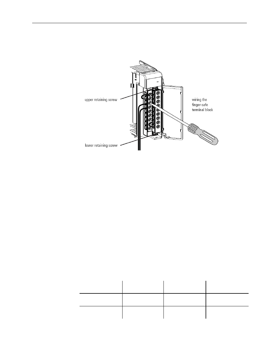
To remove the terminal block, loosen the upper and lower retaining screws. The terminal
block will back away from the module as you remove the screws. Be careful not to
damage the CJC sensors. When replacing the terminal block, torque the retaining screws
to 0.46 Nm (4.1 in-lbs).
3.7.5
Wiring the Finger Safe Terminal Block
When wiring the terminal block, keep the finger-safe cover in place.
1)
Loosen the terminal screws to be wired.
2)
Route the wire under the terminal pressure plate. You can use the bare wire or a
spade lug. The terminals accept a 6.35 mm (0.25 in.) spade lug.
Note: The terminal screws are non-captive. Therefore, it is possible to use a ring lug
[maximum 1/4 inch o.d. with a 0.139 inch minimum i.d. (M3.5)] with the module.
3)
Tighten the terminal screw making sure the pressure plate secures the wire.
Recommended torque when tightening terminal screws is 0.68 Nm (6 in-lbs).
Note: If you need to remove the finger-safe cover, insert a screwdriver into one of the
square, wiring holes and gently pry the cover off. If you wire the terminal block with
the finger-safe cover removed, you may not be able to put it back on the terminal block
because the wires will be in the way.
Wire Size and Terminal Screw Torque
Each terminal accepts up to two wires with the following restrictions:
Wire Type
Wire Size
Terminal Screw
Torque
Retaining Screw
Torque
Solid Cu-90°C
(194°F)
#14 to #22 AWG
0.68 Nm (6 in-lbs) 0.46 Nm (4.1 in-
lbs)
Stranded Cu-90°C
(194°F)
#16 to #22 AWG
0.68 Nm (6 in-lbs) 0.46 Nm (4.1 in-
lbs)