OPTI-UPS DS120KC33 User Manual
Page 5
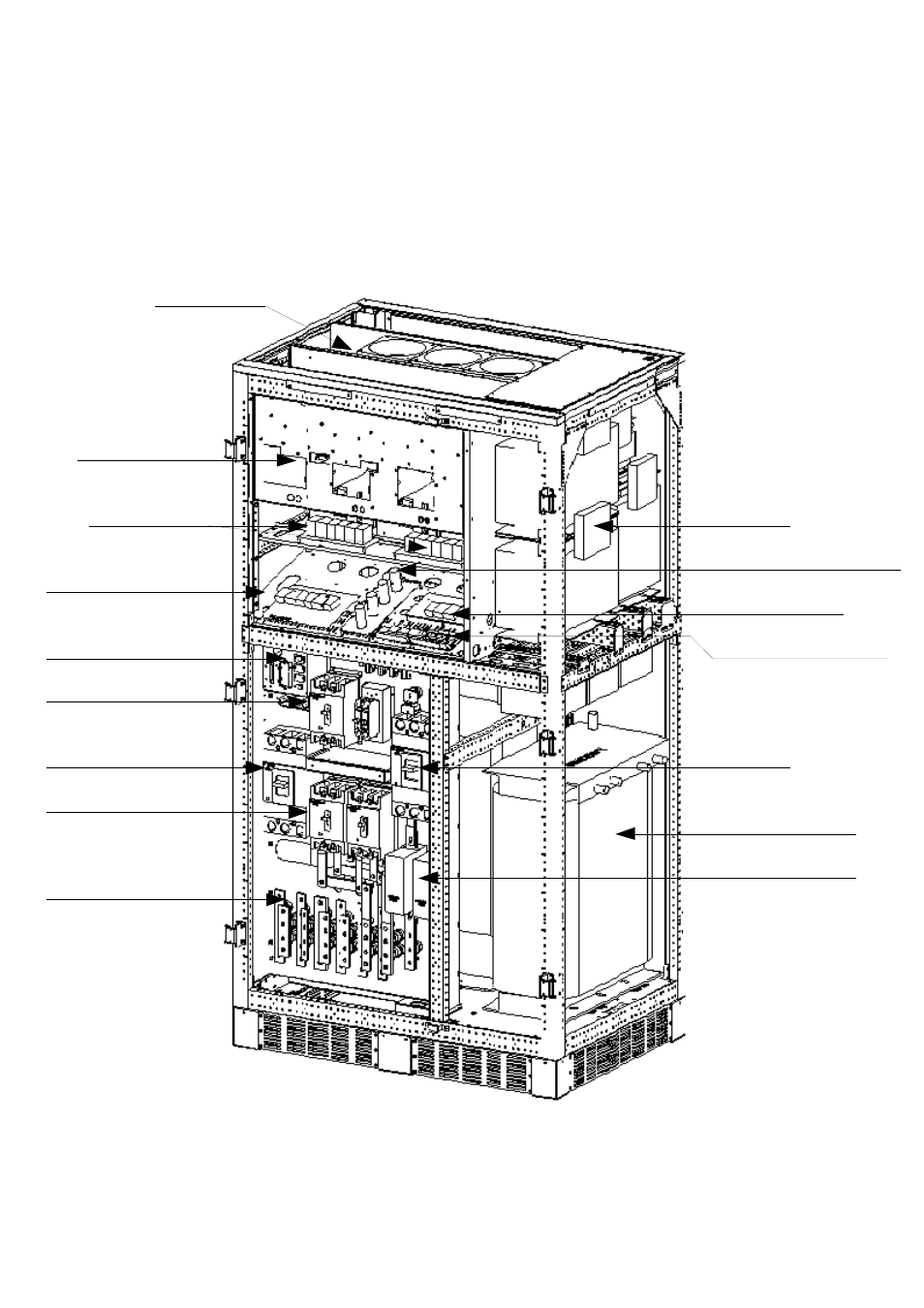
2-2 System assembly and parts layout
Drawings 2-2A and 2-2B are the assembly diagrams of DS-C33 series 100K, 120K
Fig. 2-2A
Fan
INV/Driver Board
DSP Control Board
Communication Port
S2/S1 Switch
S3 Switch
S6/S5 Switch
Input/Output
Terminal
INV Module
Input AC Choke
AC Power Sensor Board
AS-400 Interface Card
System Power Board
S4 Switch
System Transformer
S4 Battery Fuse