4 system operation mode – OPTI-UPS DS120KC33 User Manual
Page 16
2-4 System operation mode
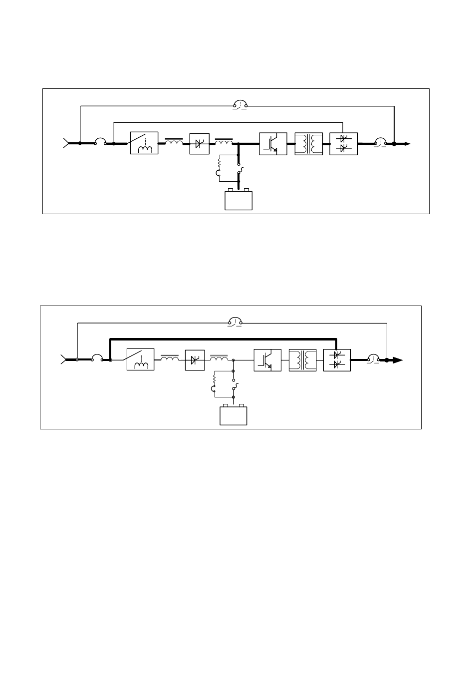
2-4-1 System is normal (Fig. 2-4-1)
Load
Battery
Pack
+
-
Utility
S3
Input
protection
Input
switch
Manual bypass switch
S6
S.T.S.
Rectifier
S4
Battery
switch
Inverter
Transformer
S5
Output
switch
S1
Battery
auxiliary
switch
AC choke
DC choke
Fig. 2-4-1
Utility AC input supplies the rectifier /battery charger where the AC is converted into DC. Battery is
recharged while the DC is fed to the inverter module. The static switch module connects the inverter
output to the load while the bypass electricity is blocked. At this time power is supplied by inverter.
2-4-2 System bypass (fig.2-4-2)
Load
Battery
Pack
+
-
Utility
S3
Input
protection
Input
switch
Manual bypass switch
S6
S.T.S.
Rectifier
S4
Battery
switch
Inverter
Transformer
S5
Output
switch
S1
Battery
auxility
switch
AC choke
DC choke
Fig. 2-4-2
Utility input AC power supplies the load through the static switch. At this time power is supplied by
the utility.