Ntellisys, Daptive, Ressure – Nor-Cal IQ+ Adaptive Pressure Controller User Manual
Page 18: Ontrollers, 0 - devicenet interface, Overview and setup
18
18
Visit our Web Site
www.n-c.com
I
ntellIsys
A
dAptIve
p
ressure
C
ontrollers
IQ+ OP-LIT 9/08
7.0 - DeviceNet Interface
DeviceNet is a network communication protocol that provides a cost-effective
solution to low-level device networking for semiconductor equipment tools.
Process data and other information such as configuration parameters can
be communicated for up to 64 nodes per network at data rate up to 500K
baud. The DeviceNet pressure controller conforms to the ODVA & ControlNet
International, Ltd. Process Control Valve (PCV) device profile. This device
profile is available in the CIP Networks Library: Volume One, Edition 3.3 -- The
Common Industrial Protocol (CIP
TM
) of the official DeviceNet specification.
Accordingly, the purpose of this manual is to provide an overview on the basic
use of the DeviceNet communication interface as it relates to the IQ+ pressure
controller, as well as report the different options supported by the controller soft-
ware communication interface.
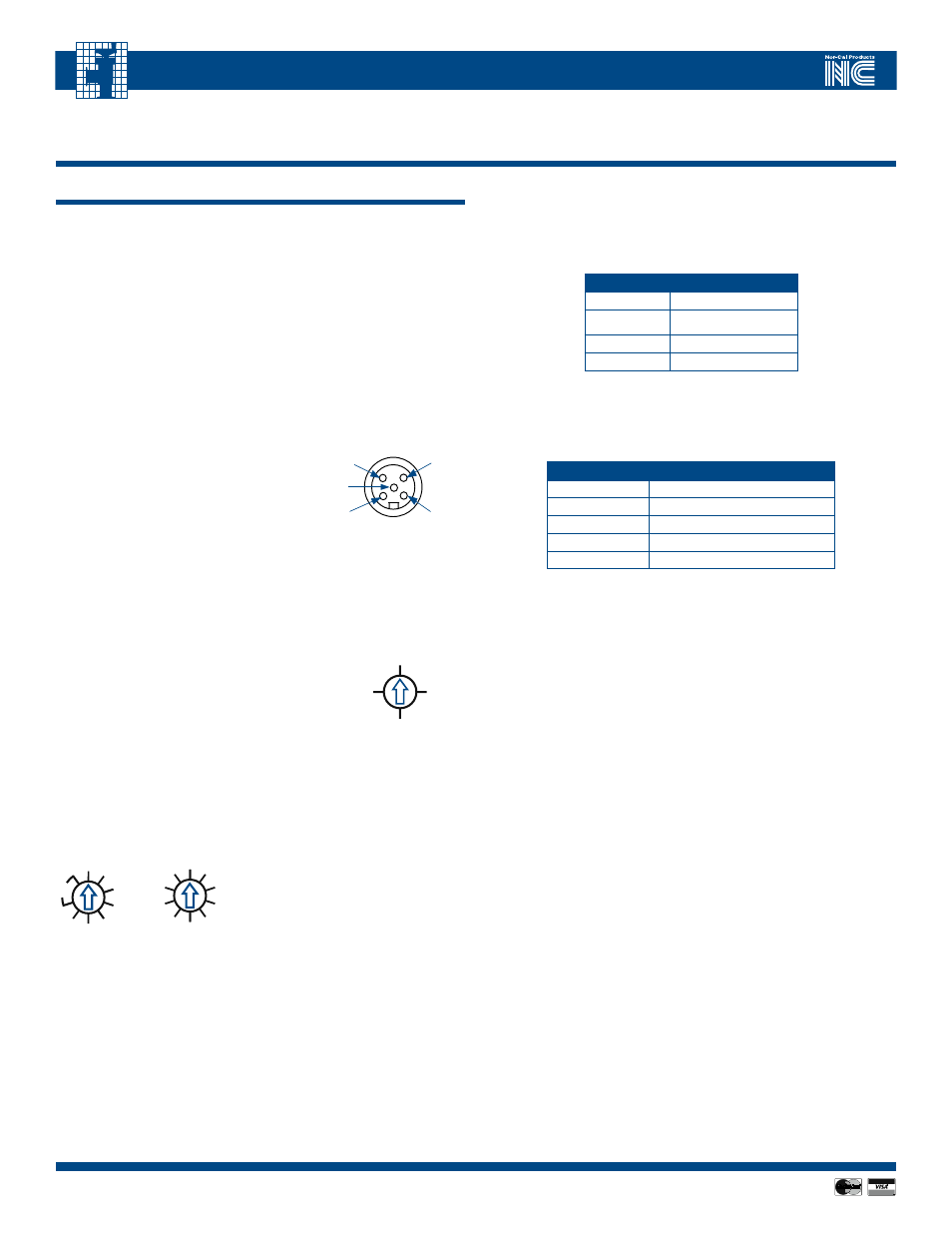
DeviceNet Connector:
The communication port is a sealed micro-
style M12 male connector that conforms
to the DeviceNet specification. The
connector pin out is shown in Figure 7.1.
DeviceNet requires power input of 11-24
VDC provided through the DeviceNet connector. Separately, the controller unit
requires a 24 VDC +/- 10% power source, which is provided through the power
connector. See section 3.0.
baud Rate Selection:
The baud rate selector as shown in Figure 7.2 is a 4
position rotary switch used to select the desired baud
rate of the controller, respectively 125Kb, 250Kb,
500Kb and software programmable.
The factory default setting is 125Kb. The software
programmable baud rate is kept
in non-volatile memory and settable through
the DeviceNet object.
mACID Selector:
Two rotary switches are used to set the MACID of the device on the network
between 0 and 63 and software programmable. Note that MACID 0 is com-
monly reserved for the DeviceNet network
master and should not be used by any device.
The factory default setting is MACID 63.
Additionally, positions 64 to 99 correspond
to the software programmable setting. The
MACID programmed in non-volatile memory
will then be used.
The software programmable MACID is
configurable via DeviceNet. However, note
that a change to the baud rate and MACID
switches only becomes effective once the
device is reset. This happens automatically
when setting the MACID in programmable
mode.
module Status:
A bicolor (red/green) Module status LED indicates the status
of the communication module according to the logic in Table 7.1.
TAbLE 7.1 - DEvICENET mODULE LED STATUS
led
StatuS
Green
Module OK
Red
Fault condition
Flashing Red
Lost DeviceNet power
OFF
No DC power
Network Status:
A bicolor (red/green) Network status LED indicates the status of the communi-
cation link according to the logic in Table 7.2.
TAbLE 7.2 - DEvICENET NETWORk LED STATUS
led
StatuS
Flashing Green
Network OK device online
Green
Network OK connection established
Flashing Red
Recoverable fault
Red
Unrecoverable fault
OFF
No network detected
No network detected:
This is an indication from the software that multiple attempts to publish a
message (typically a duplicate MACID check message) have been made but no
acknowledgement of that message has been received. It is the normal mode
of operation if the network connection is not used.
Network Ok device online:
If the device successfully detects a live bus it will transition to flashing green,
that is the standby mode, the device is ready for the master node to establish
a connection.
Network Ok connection established:
When the device has successfully been attributed a connection by the master
the network LED will transition to solid green.
Recoverable fault:
If the master unexpectedly drops the DeviceNet connection (lets the slave time
out) the LED will transition to flashing red, signaling the occurrence of a time
out fault. If the network master re-establishes the connection the device will
then recover to normal operating mode.
Unrecoverable fault:
A red Network LED signals the occurrence of a major network fault such as
two devices having the same MACID, an incompatible baud rate setting or a
short in the communication signal lines.
7.1. Overview and setup
250Kb
P
RATE
500Kb
125Kb
1 Drain
4 CAN_H
3 V-
2 V+
5 CAN_L
FIGURE 7.1 - DEvICENET
CONNECTOR PIN ASSIGNmENT
FIGURE 7.2 -
DEvICENET bAUD RATE
SELECTION SWITCH
MSD
LSD
4
6
2
8
2
4
6
P
ADDRESS
0
0
FIGURE 8.3 - DEvICENET
ADDRESS SWITCHES