Ntellisys, Daptive, Ressure – Nor-Cal IQ+ Adaptive Pressure Controller User Manual
Page 11: Ontrollers, 0 - theory of operation, Initialization sequence, Normal operation, Tuning
11
Call toll free
800-84-4166
or 530-842-4457
•
FAX 530-842-9130
I
ntellIsys
A
dAptIve
p
ressure
C
ontrollers
IQ+ OP-LIT 9/08
Initialization Sequence
When first powered up, butterfly valves with the IQ+ controller will run the
valve through an initialization sequence that lasts for approximately 30
seconds. The primary purpose for this operation is for the controller to
determine the fully open and closed points, as well as for certain motor and
position calibration steps to occur. While the initialization sequence is active,
the amber FAULT light will be illuminated and the OPEN/CLOSE LEDs both will
be extinguished. Once the initialization sequence is complete, the valve will
move to the fully open position and the green OPEN LED will
illuminate.
NOTE:
The controllers for TPV pendulum valves and TSS
gate valves contain a valve initialization safety lock function.
This safety lock will prevent valve initialization to occur until
given a “clear-to-proceed” command. The RS-232 serial
command for this is T4.
CAUTION:
Never attempt to initialize a throttle valve with
differential pressure across the sealing gate. Make sure the
pressure on both sides is equalized to ±20 Torr. Damage to
pumps and other equipment can occur otherwise.
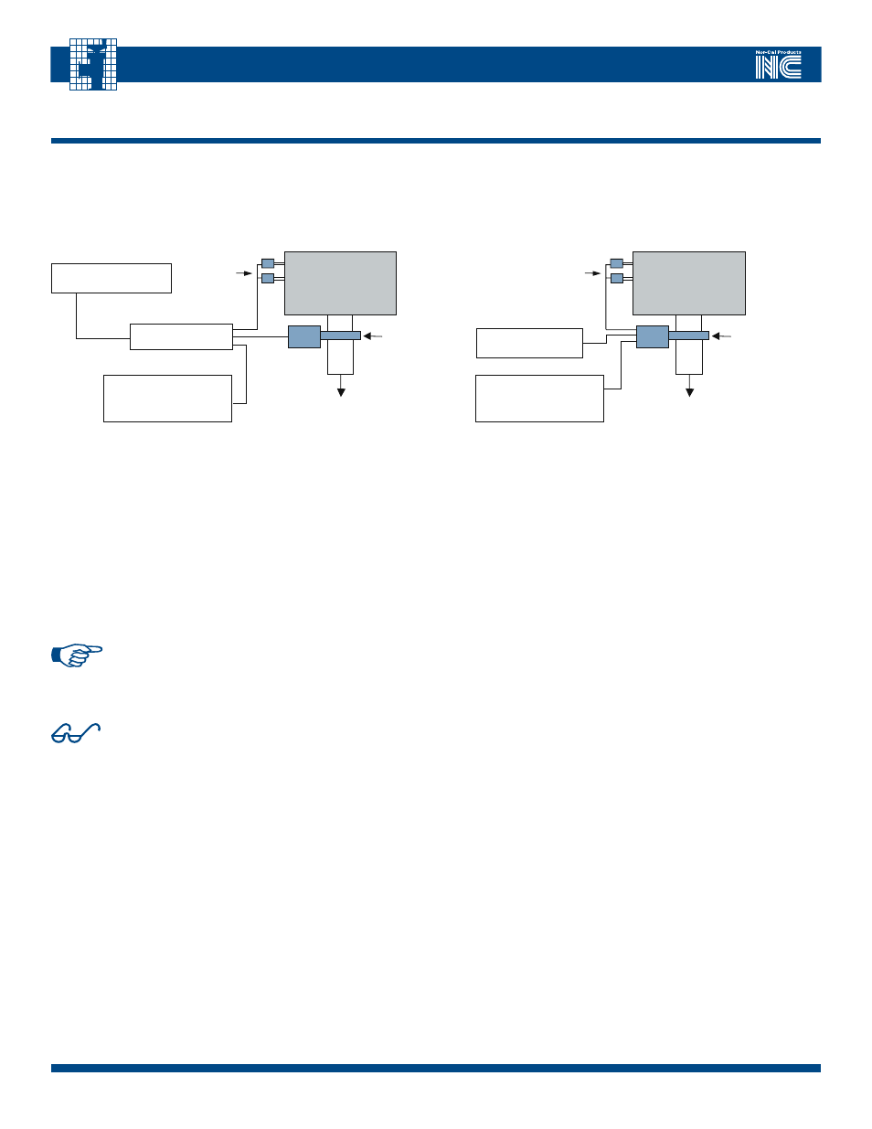
4.0 - Theory of Operation
All IQ+ controllers are designed for downstream pressure control (see Fig 4.1 and 4.2). As such, it is one of several important components in a pressure
control system. Other essential components include a host system computer, a throttle valve and one or two vacuum gauges, such as a Capacitance Diaphragm
Gauge (CDG), and a pump system. Most manufacturers’ vacuum gauges can be used to provide the vacuum measurement signal, provided they have a voltage
output proportional to pressure. The IQ+ controller requires a pressure gauge signal output that is 0-10V linear and proportional to pressure.
Vacuum Chamber
Pump
DC power supply
Host system with
RS232/485 or DeviceNet
communications
Nor-Cal
IQ+ Valve
Vacuum
gauge(s)
FIGURE 4.1 – TyPICAL INSTALLATION AND CONFIGURATION OF A bURIED
bOx IQ+ PRESSURE CONTROL SySTEm
FIGURE 4.2 – TyPICAL INSTALLATION AND CONFIGURATION
OF AN IQ+ PRESSURE CONTROL vALvE
Vacuum Chamber
Pump
DC power supply
Host system with
RS232/485 or DeviceNet
communications
IQ+ Controller
Nor-Cal
throttle
valve
Vacuum
gauge(s)
Normal Operation
After the initialization sequence is complete normal operation of the valve is
possible. There are two primary modes of operation, a) position control mode
and b) pressure control mode.
In
position control mode
, the valve will move to any position in its range
based on a position set-point command from the host. The valve will remain
in that position until instructed to do otherwise. Position control mode can
be useful in certain cases where pre-determined amount of throttling is
necessary.
Pressure control mode
, is used whenever control to a specific process
pressure level is desired. The host provides the set-point value to the
controller which, in turn, moves the valve to achieve that set point as quickly as
possible. During pressure control mode, external perturbations such as flow
changes and plasma events will automatically be compensated for by the
controller so that the pressure set-point is maintained. The value can be
changed by the host at any time.
Tuning
The IQ+ controller contains an Adaptive Pressure Control Algorithm that
has been designed to work over a wide range of flow and pressure combina-
tions. In some cases 3 system parameters may have to be adjusted. These
include system volume, system delay and speed. See Section 6.1: How to
configure IQ+ for your system.